PMF18WE1 Microchip Technology, PMF18WE1 Datasheet - Page 24
PMF18WE1
Manufacturer Part Number
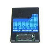
PMF18WE1
Description
PROCESSOR MODULE FOR ICE4000
Manufacturer
Microchip Technology
Datasheet
1.ICE4000.pdf
(98 pages)
Specifications of PMF18WE1
Module/board Type
Processor Module
Product
Microcontroller Modules
Core Processor
PIC18F6585/6680/8585/8680
Lead Free Status / RoHS Status
Contains lead / RoHS non-compliant
For Use With/related Products
ICE4000
Lead Free Status / RoHS Status
Lead free / RoHS Compliant, Contains lead / RoHS non-compliant


MPLAB
3.7
DS51490A-page 18
SETTING UP MISCELLANEOUS HARDWARE
ICE 4000 User’s Guide
3.6.2
MPLAB ICE 4000 can use the processor clock on the target board as long as target
board (external) power is being used. It can determine the frequency of the target board
clock and use it for displaying timing information.
1. Select the target board Oscillator Type (Section 3.3.3 “Oscillator Settings”).
2. Select the Power tab of the Debugger>Settings dialog and set Processor Power
3. Select the Clock tab on the Debugger>Settings dialog. Then select Use Target
4. Click Apply.
In addition to the settings you have already made, there are other settings that you may
or may not wish to change in the Debugger>Settings dialog. Depending on the device
you have chosen, these tabs may or may not be available and may look different for
different devices.
3.7.1
Use the Break Options tab to change the global break and trace point environment
options. These include Global Hardware Break Enable (for complex trigger usage) and
Freeze Peripherals on Halt. If enabled in the configuration bits
(Configure>Configuration Bits), you may set stack and watchdog timer break options.
3.7.2
Some parts allow device memory to be supplemented or replaced by off-chip (external)
memory. Memory modes are selected using configuration bits
(Configure>Configuration Bits).
Devices that support Microcontroller mode only do not have a Memory tab. Devices
that support Extended Microcontroller mode and/or Microprocessor mode will display
the Memory tab.
Note: There are several limitations concerning external memory, some of them
to From Target Board (see Section 3.5.2 “Processor Power from Target
Board”).
Board Clock.
The target board clock frequency will be calculated, displayed and used for any
internal time calculations. A warning is issued if the frequency is less than 32
kHz.
Because of measurement error, the calculated frequency may not be what is
desired for internal time calculations. (e.g., Your crystal oscillator has a frequency
of 8 MHz ± 50 ppm, but the target frequency is shown as 7.993755.)
Measurement error can range from 3.9% to a fraction of a percent.
Note: If MPLAB ICE 4000 is not hooked up to a target board and you click
Using a Target Board Clock
Settings Dialog, Break Options Tab
Settings Dialog, Memory Tab
device-dependent. Please see the limitations section of the on-line help file
for more information.
Use Target Board Clock, you will get a warning dialog.
2004 Microchip Technology Inc.
Related parts for PMF18WE1
Image
Part Number
Description
Manufacturer
Datasheet
Request
R

Part Number:
Description:
Manufacturer:
Microchip Technology Inc.
Datasheet:
Part Number:
Description:
Manufacturer:
Microchip Technology Inc.
Datasheet:
Part Number:
Description:
Manufacturer:
Microchip Technology Inc.
Datasheet:
Part Number:
Description:
Manufacturer:
Microchip Technology Inc.
Datasheet:
Part Number:
Description:
Manufacturer:
Microchip Technology Inc.
Datasheet:
Part Number:
Description:
Manufacturer:
Microchip Technology Inc.
Datasheet:
Part Number:
Description:
Manufacturer:
Microchip Technology Inc.
Datasheet:
Part Number:
Description:
Manufacturer:
Microchip Technology Inc.
Datasheet: