PMF18WE1 Microchip Technology, PMF18WE1 Datasheet - Page 62
PMF18WE1
Manufacturer Part Number
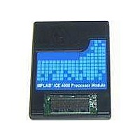
PMF18WE1
Description
PROCESSOR MODULE FOR ICE4000
Manufacturer
Microchip Technology
Datasheet
1.ICE4000.pdf
(98 pages)
Specifications of PMF18WE1
Module/board Type
Processor Module
Product
Microcontroller Modules
Core Processor
PIC18F6585/6680/8585/8680
Lead Free Status / RoHS Status
Contains lead / RoHS non-compliant
For Use With/related Products
ICE4000
Lead Free Status / RoHS Status
Lead free / RoHS Compliant, Contains lead / RoHS non-compliant


MPLAB
7.5
DS51490A-page 56
REAL-TIME READS
ICE 4000 User’s Guide
7.4.4
Reading the information in the trace memory window requires knowledge of device
architecture. PICmicro MCU instructions fetch one instruction cycle while decoding and
executing the previous cycle, (i.e., there is a one cycle pipeline).
In the example below:
1. At line 2, the W register (address = 0xfe8) is cleared.
2. The next cycle, the value gets written into the W register, i.e., the W register value
FIGURE 7-4:
This feature consists of a real-time read buffer that records the data of all processor file
register write operations. The address and data are obtained from the file register
address and data bus. The write operation to the real-time read buffer occurs after data
buffers have latched the information from the file register address and data bus.
The real-time display (either Watch, File Register or SFR window) gives a dynamic
display of data, which is being continuously captured in real time. The values displayed
are the values that are collected from the last read of the real-time read buffer. The time
interval between real-time reads is set up under the Debugger>Settings, View tab.
Note: A longer time interval than the default value will update the values at a
of 0xFF is changed to 0x00.
Reading the Trace Memory Window
much slower pace, making it easier to monitor values.
TRACE MEMORY WINDOW EXAMPLE, PIC18F452
1
2
2004 Microchip Technology Inc.
Related parts for PMF18WE1
Image
Part Number
Description
Manufacturer
Datasheet
Request
R

Part Number:
Description:
Manufacturer:
Microchip Technology Inc.
Datasheet:
Part Number:
Description:
Manufacturer:
Microchip Technology Inc.
Datasheet:
Part Number:
Description:
Manufacturer:
Microchip Technology Inc.
Datasheet:
Part Number:
Description:
Manufacturer:
Microchip Technology Inc.
Datasheet:
Part Number:
Description:
Manufacturer:
Microchip Technology Inc.
Datasheet:
Part Number:
Description:
Manufacturer:
Microchip Technology Inc.
Datasheet:
Part Number:
Description:
Manufacturer:
Microchip Technology Inc.
Datasheet:
Part Number:
Description:
Manufacturer:
Microchip Technology Inc.
Datasheet: