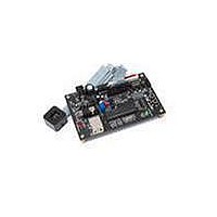
HDJD-JD05 Avago Technologies US Inc., HDJD-JD05 Datasheet - Page 5

HDJD-JD05
Manufacturer Part Number
HDJD-JD05
Description
KIT DEV RGB COLOR SENSOR 20-QFN
Manufacturer
Avago Technologies US Inc.
Specifications of HDJD-JD05
Sensor Type
Light, Color Sensor
Sensing Range
RGB
Interface
2-Wire Serial
Voltage - Supply
2.5 V ~ 3.6 V
Embedded
No
Utilized Ic / Part
ADJD-S313-QR999
For Use With/related Products
ADJD-S313-QR999
Lead Free Status / RoHS Status
Not applicable / Not applicable
Transmissive Color Sensing Theory of Operation
By transmissive, it means the application kit is placed
facing the light source being measured. The filter-coated
photodiode array of the color sensor converts the R, G,
B components of light falling on it into photocurrent,
which is then converted into digital values for each of
the primary component. Given that any colored light is
uniquely represented by the ratio of the primary colors,
the color sensor provides a definite manner of measuring
color. In addition, the sensor is also responsive to light in-
tensity where its outputs increase linearly with increasing
light intensity. For a given light source, the application kit
can also be used to determine the color of transparent
medium through which the light is passed before reach-
ing the sensor. For example, the medium could be glass,
plastic or liquid.
Figure 3.2: R, G, B outputs of the sensor is determined by color of light falling on
the sensor
Figure 3.3: Apply color sensor on media such as color filter, gas or liquid
To use HDJD-JD05 in transmissive mode, the white LED
should be turn off with the slider switch at the digital
color sensor controller board.
Figure 3.4: 2-wire serial interface to USB Converter Block Diagram
Figure 3.5: Power Module Block Diagram
Digital Color
Sensor
ADJD-S313
adapter
Power
12V
SCL, SDA
@2.6V
Linear regulator, LM7805
Adjustable regulator, LM317
Dual Bidirectional
Bus Buffer
P82B96
SCL, SDA
@5V
3.1 Digital Color Sensor Controller Board
The digital color sensor controller board consists of the
following modules:
(i) 2-wire Serial Interface to USB Converter Module
(ii) Power Supply Module
(iii) LED Constant Current Module
(iv) Digital Color Sensor Reset and Sleep Module
2-wire Serial Interface to USB Converter Module
This module converts the 2-wire serial interface from the
digital color sensor to USB protocol that can be easily
interface with the computer. The main components of
this module are dual bidirectional bus buffer, P82B96 and
USB microcontroller, PIC18F2455. The P82B96 interface
the two different logic level from the microcontroller (5V)
and digital color sensor (2.6V) while the microcontroller
interface the 2 wire serial to USB.
See figure 3.4
Power Supply Module
The power supply module taps power from the adapter
and provides regulated voltage 5V for the microcon-
troller and 2.6V for the digital color sensor.
See figure 3.5
USB
Microcontroller
PIC18F2455
5V
2.6V
To PC via
USB cable


