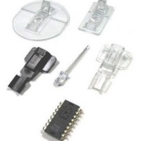
ADNK-3061 Avago Technologies US Inc., ADNK-3061 Datasheet - Page 2

ADNK-3061
Manufacturer Part Number
ADNK-3061
Description
KIT REFERENCE DESIGN ADNK-3060
Manufacturer
Avago Technologies US Inc.
Specifications of ADNK-3061
Main Purpose
Reference Design, Optical Mouse
Utilized Ic / Part
ADNS-3060, CY7C63743-PC
Description/function
Optical Mouse Sensor Kit
Interface Type
USB
Product
Display Modules
Touch Panel
No Touch Panel
For Use With/related Products
CY7C63743-PC
Lead Free Status / RoHS Status
Lead free / RoHS Compliant
Lead Free Status / RoHS Status
Lead free / RoHS Compliant, Lead free / RoHS Compliant
Mouse Optics
The of Z-wheel motion is detected using the traditional
method by decoding the quadrature signal generated
by optical encoder. Two phototransistors are connected
in a sourcefollower configuration. An infrared LED
shines, causing the phototran-sistors to turn on. In
between the phototransistors and LED is a pinwheel
that turns on the mouse ball rollers. The fan of this
pinwheel is mechanically designed to block the infrared
light such that the phototran-sistors are turned on and
off in a quadrature output pattern. Every change in the
phototransistor outputs represents a count of wheel
movement. Comparing the last state of the optics to the
current state derives direction information. As shown
in Figure 1, traveling along the quadrature signal to
the right produces a unique set of state transitions, and
traveling to the left produces another set of unique state
transitions. For a lower power system solution, using a
mechanical z-wheel is recommended instead of a Z LED
and Optical Encoder combination.
Q1.1 output
Q1.3 output
Figure 1. Optics Quadrature Signal Generation.
Mouse Buttons
Mouse buttons are connected as standard switches.
These switches are pulled up by the pull up resistors
inside the microcontroller. When the user presses a
button, the switch will be closed and the pin will be
pulled LOW to GND. A LOW state at the pin is interpreted
as the button being pressed. A HIGH state is interpreted
as the button has been released or the button is not
being pressed. Normally the switches are debounced in
firmware for 15–20 ms. In this reference design there are
three switches: left, Z-wheel, and right.
2
Infrared
LED
transistors
Photo-
Introduction to the CY7C63743-PC
The CY7C63743-PC is an 8-bit RISC microcontroller with
an integrated USB Serial Interface Engine (SIE). The ar-
chitecture executes general-purpose instructions that
are optimized for USB applications. The CY7C63743-PC
has a built-in clock oscillator and timers, as well as pro-
grammable drive strength, and pull-up resistors on each
I/O line. High performance, low-cost human interface
type computer peripherals can be implemented with a
minimum of external components and firmware effort.
Serial Peripheral Interface (SPI)
The CY7C63743-PC provides a SPI compatible interface.
The SPI circuit supports byte serial transfer in either
Master or Slave mode. The integrated SPI circuit allows
the CY7C63743-PC to communicate with an external
SPI compatible hardware, in this case the ADNS-3060
sensor.
Hardware Implementation
The standard hardware to implement a mouse is shown
in Figure 2. For X and Y movement, the optical mouse
sensor is used. The Z wheel movement is detected by
another set of optical encoder that outputs quadrature
signals. For each button there is a switch that is pulled up
internally by the built-in in pull up resistors. The D-line is
pulled up via a 1.3k ohm resistor connected to the VREG
pin.
Firmware Configurable GPIO
The reference firmware is configured to use the GPIO pins
as shown in the schematic under Appendix A. However, it
may be more optimal to use a different I/O configuration
to meet the mechanical constraints of PCB design. The
reference firmware is designed to be easily configured
to another set of pin connections. This is accomplished
through changes in the I/O definitions at the beginning
of the adns- 3060.asm listing. The following statements
are the pin definitions as they exist today. The firmware
will use these definitions to read and configure the GPIO
pins, without any other modifications.


