ADIS16255/PCBZ Analog Devices Inc, ADIS16255/PCBZ Datasheet - Page 14
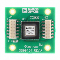
ADIS16255/PCBZ
Manufacturer Part Number
ADIS16255/PCBZ
Description
BOARD EVAL FOR ADIS16255
Manufacturer
Analog Devices Inc
Series
iMEMS®, iSensor™r
Specifications of ADIS16255/PCBZ
Sensor Type
Gyroscope, 1 Axis (Yaw Rate)
Sensing Range
±80°/sec, ±160°/sec, ±320°/sec
Interface
SPI Serial
Sensitivity
0.018°/sec/LSB
Voltage - Supply
4.75 V ~ 5.25 V
Embedded
No
Utilized Ic / Part
ADIS16255
For Use With
ADISUSBZ - KIT EVAL ADIS W/SOFTWARE USBADISEVALZ - KIT PC EVALUATION W/SOFTWARE
Lead Free Status / RoHS Status
Lead free / RoHS Compliant
Available stocks
Company
Part Number
Manufacturer
Quantity
Price

Part Number:
ADIS16255/PCBZ
Manufacturer:
ADI/亚德诺
Quantity:
20 000


ADIS16250/ADIS16255
CALIBRATION
The ADIS16250/ADIS16255 are factory-calibrated for
sensitivity and bias. It also provides several user calibration
functions for simplifying field-level corrections. The calibra-
tion factors are stored in nonvolatile memory and are applied
using the following linear calibration equation:
where:
y is the calibrated output data.
x is the precalibration data.
m is the sensitivity scale factor.
b is the offset scale factor.
There are three options for system-level calibrations of the
bias in the ADIS16250/ADIS16255: auto-null, factory
calibration restore, and manual calibration updates. The
auto-null and factory reset options are described in the
Global Commands section. Optional field-level calibrations
use the preceding equation and require two steps:
1.
2.
The GYRO_OFF provides a calibration range of ±37.5°/sec,
and its contents are nonvolatile. The GYRO_SCALE register
provides a calibration range of 0 to 1.9995, and its contents
are also nonvolatile.
Table 9. GYRO_OFF Register Definition
Address
0x15,
0x14
1
Table 10. GYRO_OFF Bit Descriptions
Bit
15:12
11:0
Table 11. GYRO_SCALE Register Definition
Address
0x17, 0x16
1
2
Table 12. GYRO_SCALE Bit Descriptions
Bit
15:12
11:0
Scale is the weight of each LSB.
Scale is the weight of each LSB.
Equates to a scale factor of one.
y = mx + b
Characterize the behavior of the ADIS16250/ADIS16255
at predefined critical operating conditions.
Use this characterization data to calculate and load the
contents of GYRO_OFF (b) and GYRO_SCALE (m).
Scale
0.018315°/sec
Description
Not used
Data bits
Description
Not used
Data bits
Scale
0.0487%
1
1
Default
0x0800
Default
0x0000
2
Format
Twos
complement
Format
Binary
Access
R/W
Access
R/W
Rev. D | Page 14 of 20
GLOBAL COMMANDS
The ADIS16250/ADIS16255 provide global commands for common
operations such as auto-null, factory calibration restore, manual
flash update, auxiliary DAC latch, and software reset. Each of these
global commands has a unique control bit assigned to it in the
COMMAND register and is initiated by writing a 1 to its assigned bit.
The auto-null function does two things: it resets the contents of the
ANGL_OUT register to zero, and it adjusts the GYRO_OUT register
to zero. This automated adjustment takes two steps:
1.
2.
For optimal calibration accuracy, set the number of filtering taps to
its maximum, wait for the appropriate number of samples to
process through the filter, and then exercise this option.
The factory calibration restore command sets the contents of
GYRO_OFF to 0x0000 and GYRO_SCALE to 0x0800, erasing any
field-level calibration contents. The manual flash update writes the
contents of each nonvolatile register into flash memory for storage.
This process takes approximately 50 ms and requires the power
supply voltage to be within specification for the duration of the
event. It is worth noting that this operation also automatically
follows the auto-null and factory reset commands.
The DAC latch command loads the contents of AUX_DAC into the
DAC latches. Since the AUX_DAC contents must be updated one
byte at a time, this command ensures a stable DAC output voltage
during updates. Finally, the software reset command sends the
ADIS16250/ADIS16255 digital processor into a restart sequence,
effectively doing the same thing as the RST line.
Table 13. COMMAND Register Definition
Address
0x3F, 0x3E
Table 14. COMMAND Bit Descriptions
Bit
15:8
7
6:4
3
2
1
0
Read GYRO_OUT.
Write the opposite of this value into the GRYO_OFF register.
Sensor noise influences the accuracy of this step.
Description
Not used
Software reset command
Not used
Manual flash update command
Auxiliary DAC data latch
Factory calibration restore command
Auto-null command
Default
N/A
Format
N/A
Access
Write only
Related parts for ADIS16255/PCBZ
Image
Part Number
Description
Manufacturer
Datasheet
Request
R

Part Number:
Description:
±1.7g Dual-Axis IMEMS Accelerometer Evaluation Board
Manufacturer:
Analog Devices Inc
Datasheet:

Part Number:
Description:
Inertial Sensor Evaluation System
Manufacturer:
Analog Devices Inc
Datasheet:
Part Number:
Description:
Manufacturer:
Analog Devices Inc
Datasheet:
Part Number:
Description:
Manufacturer:
Analog Devices Inc
Datasheet:
Part Number:
Description:
Manufacturer:
Analog Devices Inc
Datasheet:
Part Number:
Description:
Manufacturer:
Analog Devices Inc
Datasheet:
Part Number:
Description:
Manufacturer:
Analog Devices Inc
Datasheet:
Part Number:
Description:
Manufacturer:
Analog Devices Inc
Datasheet:
Part Number:
Description:
Manufacturer:
Analog Devices Inc
Datasheet:
Part Number:
Description:
Manufacturer:
Analog Devices Inc
Datasheet:
Part Number:
Description:
Manufacturer:
Analog Devices Inc
Datasheet:
Part Number:
Description:
Manufacturer:
Analog Devices Inc
Datasheet:
Part Number:
Description:
Manufacturer:
Analog Devices Inc
Datasheet: