ADIS16255/PCBZ Analog Devices Inc, ADIS16255/PCBZ Datasheet - Page 18
ADIS16255/PCBZ
Manufacturer Part Number
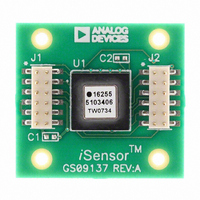
ADIS16255/PCBZ
Description
BOARD EVAL FOR ADIS16255
Manufacturer
Analog Devices Inc
Series
iMEMS®, iSensor™r
Specifications of ADIS16255/PCBZ
Sensor Type
Gyroscope, 1 Axis (Yaw Rate)
Sensing Range
±80°/sec, ±160°/sec, ±320°/sec
Interface
SPI Serial
Sensitivity
0.018°/sec/LSB
Voltage - Supply
4.75 V ~ 5.25 V
Embedded
No
Utilized Ic / Part
ADIS16255
For Use With
ADISUSBZ - KIT EVAL ADIS W/SOFTWARE USBADISEVALZ - KIT PC EVALUATION W/SOFTWARE
Lead Free Status / RoHS Status
Lead free / RoHS Compliant
Available stocks
Company
Part Number
Manufacturer
Quantity
Price

Part Number:
ADIS16255/PCBZ
Manufacturer:
ADI/亚德诺
Quantity:
20 000


ADIS16250/ADIS16255
Flash Memory Endurance
The ENDURANCE register maintains a running count of writes
to the flash memory. It provides up to 32,768 counts. Note that
if this count is exceeded, the register wraps around, and goes
back to zero, before beginning to increment again.
Table 30. ENDURANCE Register Definition
Address
0x01, 0x00
Alarms
The ADIS16250/ADIS16255 provide two independent alarm
options for event detection. Event detections occur when output
register data meets the configured conditions. Configuration
options are:
•
•
•
•
•
The ALM_MAG1 register and the ALM_MAG2 register both
establish the threshold level for detecting events. They take on the
format of the source data and provide a bit for establishing the
greater than/less than comparison direction. When making
dynamic comparisons, the ALM_SMPL1 register and the
ALM_SMPL2 register establish the number of averages taken for
the source data as a reference for comparison. In this configuration,
each subsequent source data sample is subtracted from the previous
one, establishing an instantaneous delta. The ALM_CTRL register
controls the source data selection, static/dynamic selection, filtering
selection, and digital I/O usage for the alarms.
The rate of change calculation is
where:
N
y(n) is the sampled output data.
M
Y
> or < is determined by the MSB in ALM_MAG1/2.
C
DS
C
is the factor to be compared with M
is the magnitude for comparison in ALM_MAG1/2.
is the number of samples in ALM_SMPL1/2.
All output data registers are available for monitoring as the
source data.
The source data can be filtered or unfiltered.
Comparisons can be static or dynamic (rate of change).
The threshold levels and times are configurable.
Comparison can be greater than or less than.
Y
Rate
C
=
of
N
1
change
DS
N
n
Default
N/A
∑
=
DS
1
y
alarm
(
n
+
) 1
⇒
−
y
is
(
n
Y
Format
Binary
)
C
>
or
C
.
<
M
C
?
Access
Read-only
Rev. D | Page 18 of 20
Table 31. ALM_MAG1 Register Definition
Address
0x21, 0x20
Table 32. ALM_MAG1 Bit Descriptions
Bit
15
14
13:0
Table 33. ALM_SMPL1 Register Definition
Address
0x25, 0x24
Table 34. ALM_SMPL1 Bit Descriptions
Bit
15:8
7:0
Table 35. ALM_MAG2 Register Definition
Address
0x23, 0x22
Table 36. ALM_MAG2 Bit Descriptions
Bit
15
14
13:0
Table 37. ALM_SMPL2 Register Definition
Address
0x27, 0x26
Table 38. ALM_SMPL2 Bit Designations
Bit
15:8
7:0
Table 39. ALM_CTRL Register Definition
Address
0x29, 0x28
Description
Comparison polarity
Not used
Data bits: format matches source data format
1 = greater than
0 = less than
Description
Comparison polarity: 1 = greater than, 0 = less than
Not used
Data bits: format matches source data format
Description
Not used
Data bits
Description
Not used
Data bits
Default
0x0000
Default
0x0000
Default
0x0000
Default
0x0000
Default
0x0000
Format
N/A
Format
Binary
Format
N/A
Format
Binary
Format
N/A
Access
R/W
Access
R/W
Access
R/W
Access
R/W
Access
R/W
Related parts for ADIS16255/PCBZ
Image
Part Number
Description
Manufacturer
Datasheet
Request
R

Part Number:
Description:
±1.7g Dual-Axis IMEMS Accelerometer Evaluation Board
Manufacturer:
Analog Devices Inc
Datasheet:

Part Number:
Description:
Inertial Sensor Evaluation System
Manufacturer:
Analog Devices Inc
Datasheet:
Part Number:
Description:
Manufacturer:
Analog Devices Inc
Datasheet:
Part Number:
Description:
Manufacturer:
Analog Devices Inc
Datasheet:
Part Number:
Description:
Manufacturer:
Analog Devices Inc
Datasheet:
Part Number:
Description:
Manufacturer:
Analog Devices Inc
Datasheet:
Part Number:
Description:
Manufacturer:
Analog Devices Inc
Datasheet:
Part Number:
Description:
Manufacturer:
Analog Devices Inc
Datasheet:
Part Number:
Description:
Manufacturer:
Analog Devices Inc
Datasheet:
Part Number:
Description:
Manufacturer:
Analog Devices Inc
Datasheet:
Part Number:
Description:
Manufacturer:
Analog Devices Inc
Datasheet:
Part Number:
Description:
Manufacturer:
Analog Devices Inc
Datasheet:
Part Number:
Description:
Manufacturer:
Analog Devices Inc
Datasheet: