INDART-ONE/FSL SofTec Microsystems SRL, INDART-ONE/FSL Datasheet - Page 88
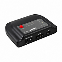
INDART-ONE/FSL
Manufacturer Part Number
INDART-ONE/FSL
Description
PROG/DEBUG FOR HC08/HCS08/HCS12
Manufacturer
SofTec Microsystems SRL
Series
inDARTr
Type
In-Circuit, Real-Time Debugger/Programmerr
Datasheets
1.INDART-ONEFSL.pdf
(2 pages)
2.INDART-ONEFSL.pdf
(140 pages)
3.INDART-ONEFSL.pdf
(2 pages)
Specifications of INDART-ONE/FSL
Contents
In-circuit debugger/programmer unit, Cables, Evaluation Board and Software
For Use With/related Products
Freescale HC08/S08/RS08/S12/S12X
Lead Free Status / RoHS Status
Lead free / RoHS Compliant
Other names
520-1038
INDART-ONE
INDART-ONE


6
Working with HCS08 Devices
low clock frequency will result in slow BDM communication (and therefore
slow debugging and slow programming), while a clock frequency which
changes frequently (as in the case of the user application modifying the FLL
peripheral) may result in loss of BDM communication.
6.1.2 Fast Programming
The “Enable Fast Programming” parameter (available on some devices), if
selected, speeds up programming by driving the microcontroller’s internal
PLL circuitry to the maximum settings.
6.1.3 Trimming
Some devices can have their internal oscillator calibrated (trimmed) through
the “VCO Bus Frequency” parameter (please note that other devices may
present different calibration parameters).
6.1.4 Other Settings
The “TARGET POWER OUT Voltage” parameter specifies the voltage
provided by inDART-One on the “TARGET POWER OUT” connector, which
can be used to power up the target board.
The “RESET Rise Time” parameter specifies the time, in milliseconds,
needed for the target RESET signal to go high. This value depends on the
target system, and is used by inDART-One to generate the appropriate delay
before to drive the BKGD line correctly in order to enter the special single
chip mode. The default value of 20 ms is appropriate for most systems.
86
i
Note: only the central pin of the “TARGET POWER OUT”
connector is used, while the outer sleeve is not connected.
The GND reference is taken from the “BDM” cable.
Related parts for INDART-ONE/FSL
Image
Part Number
Description
Manufacturer
Datasheet
Request
R

Part Number:
Description:
KIT DEBUGGER IN-CIRC ST7 FLASH
Manufacturer:
STMicroelectronics
Datasheet:
Part Number:
Description:
KIT DEBUGGER IN-CIRC ST7 USB
Manufacturer:
STMicroelectronics
Datasheet:

Part Number:
Description:
KIT STARTER FOR ST7
Manufacturer:
SofTec Microsystems SRL
Datasheet:
Part Number:
Description:
KIT DESIGN FOR ST7
Manufacturer:
SofTec Microsystems SRL
Datasheet:
Part Number:
Description:
KIT DESIGN USB FOR HCO8
Manufacturer:
SofTec Microsystems SRL
Datasheet:
Part Number:
Description:
KIT DESIGN USB FOR HCO8
Manufacturer:
SofTec Microsystems SRL
Datasheet:

Part Number:
Description:
KIT DESIGN USB FOR HCO8
Manufacturer:
SofTec Microsystems SRL
Datasheet:
Part Number:
Description:
KIT DESIGN USB FOR HCO8
Manufacturer:
SofTec Microsystems SRL
Datasheet:
Part Number:
Description:
KIT DESIGN USB FOR HCS12
Manufacturer:
SofTec Microsystems SRL
Datasheet:
Part Number:
Description:
KIT DESIGN USB FOR HCS12
Manufacturer:
SofTec Microsystems SRL
Datasheet:
Part Number:
Description:
KIT DESIGN USB FOR HCS12
Manufacturer:
SofTec Microsystems SRL
Datasheet:
Part Number:
Description:
KIT DESIGN USB FOR HCO8
Manufacturer:
SofTec Microsystems SRL
Datasheet:
Part Number:
Description:
KIT DESIGN USB FOR HCO8
Manufacturer:
SofTec Microsystems SRL
Datasheet:
Part Number:
Description:
KIT DESIGN USB FOR HCO8
Manufacturer:
SofTec Microsystems SRL
Datasheet:

Part Number:
Description:
KIT DESIGN USB FOR HCSO8
Manufacturer:
SofTec Microsystems SRL
Datasheet: