G2R-1-DC24 Omron, G2R-1-DC24 Datasheet - Page 15
G2R-1-DC24
Manufacturer Part Number
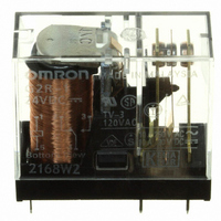
G2R-1-DC24
Description
RELAY PWR SPDT 10A 24VDC PCB
Manufacturer
Omron
Series
G2Rr
Datasheets
1.G2R-1A-E-DC12.pdf
(14 pages)
2.G2R-1A-E-DC12.pdf
(30 pages)
3.G2R-2-SND_DC24S.pdf
(19 pages)
4.G2R-1AE-DC24.pdf
(15 pages)
Specifications of G2R-1-DC24
Relay Type
General Purpose
Contact Form
SPDT (1 Form C)
Contact Rating (current)
10A
Switching Voltage
380VAC, 125VDC - Max
Coil Type
Standard
Coil Current
21.8mA
Coil Voltage
24VDC
Turn On Voltage (max)
16.8 VDC
Turn Off Voltage (min)
3.6 VDC
Mounting Type
Through Hole
Termination Style
PC Pin
Circuit
SPDT (1 Form C)
Contact Rating @ Voltage
10A @ 250VAC
Control On Voltage (max)
16.8 VDC
Control Off Voltage (min)
3.6 VDC
Coil Voltage Vdc Nom
24V
Contact Current Max
10A
Contact Voltage Ac Nom
250V
Contact Voltage Dc Nom
30V
Coil Resistance
1100ohm
Contact Configuration
SPDT
Current, Rating
10 A
Dielectric Rating
5000 VAC @ 50⁄60 Hz (For 1 Minute Between Coil and Contacts)
Dimensions
1.14 in. L x 0.51 in. W x 1.40 in. H
Function
Power
Number Of Pins
5
Power, Rating
2500⁄300 VA⁄W
Resistance, Coil
253 Ohms
Standards
UL, CSA, VDE, CE
Temperature, Operating, Maximum
70 °C
Temperature, Operating, Minimum
-40 °C
Termination
Through Hole
Voltage, Control
24 VDC
Voltage, Rating
380 VAC
Contact Rating
10 A
Contact Termination
Solder Pin
Mounting Style
Through Hole
Power Consumption
530 mW
Contact Material
Silver Alloy
Lead Free Status / RoHS Status
Lead free / RoHS Compliant
Lead Free Status / RoHS Status
Lead free / RoHS Compliant, Lead free / RoHS Compliant
Other names
G2R-1-DC24
G2R1DC24
Z2840
G2R1DC24
Z2840
Available stocks
Company
Part Number
Manufacturer
Quantity
Price
Company:

Part Number:
G2R-1-DC24V
Manufacturer:
OMRON
Quantity:
12 000
Company:
Part Number:
G2R-1-DC24V
Manufacturer:
NAIS
Quantity:
20 000
Part Number:
G2R-1-DC24V
Manufacturer:
OMRON欧姆龙进口
Quantity:
20 000


■ Latching Relays
• Avoid use in locations subject to excessive magnetic particles or
• Avoid use in magnetic fields (over 8,000 A•m).
• Take measures to preventing problems caused by vibration or
Drive Circuit (Dual Coil Latching Relays G5AK, G6AK, G6BK, etc.)
When a DC-switching latching relay is used in one of the circuits shown in the following diagram, the relay contacts may be released from the locked
state unless a diode (enclosed in the dotted box in the circuit diagram) is connected to the circuit.
When connecting a diode to the relay circuit, be sure to use a diode with a repetitive peak-inverse voltage, and a DC reverse voltage sufficient to
withstand external noise or surge. Also be sure that the diode has an average rectified current greater than the coil current.
If the contact of the relay is used to de-energize the relay, the relay may not operate normally. Avoid using the relay in a circuit like the one shown
below:
dust.
shock. Problems may originate from other relay(s) operating or
releasing on the same panel.
Circuit connecting two reset coils in parallel.
Circuit connecting two set coils in parallel
(+)
(−)
(+)
(−)
S
S
K
1
S
D
D
R
S
1
1
1
R
1
K
1
S
S
2
2
S
S
D
R
S
D
R
2
3
K
2
Incorrect Use:
2
K
2
S
Electromechanical Relays
3
Circuits
X
X
• Avoid simultaneous energization of the set and reset coils, even
• Avoid use under conditions where excessive surge-generating
• When planning to mount multiple relays side-by-side, observe the
b
L
X
X
though both coils can be continuously energized.
sources exist in the coil power source.
minimum mounting interval of each type of relay.
L
b
: Latching relay
: NC contact of relay
Circuit connecting set coil of latching relay
in parallel with another relay coil.
Technical Information
Circuit connecting set coil to reset coil.
(+)
(−)
Load
(+)
(−)
S
K
1
D
S
1
R
D
1
S
1
S
S
S
2
K
S
S
2
D
2
3
2
R
R
S
S
3
4
15
Related parts for G2R-1-DC24
Image
Part Number
Description
Manufacturer
Datasheet
Request
R


Part Number:
Description:
RELAY PWR SPDT 10A 12VDC PCB
Manufacturer:
Omron
Datasheet:

Part Number:
Description:
RELAY PWR SPDT 16A 18VDC PCB
Manufacturer:
Omron
Datasheet:
Part Number:
Description:
RELAY PWR SPDT 16A 120VAC PCB
Manufacturer:
Omron
Datasheet:

Part Number:
Description:
RELAY PWR SPDT 10A 120VAC PCB
Manufacturer:
Omron
Datasheet:

Part Number:
Description:
RELAY SPDT 6VDC PLUG-IN W/LED
Manufacturer:
Omron
Datasheet:
Part Number:
Description:
RELAYS
Manufacturer:
Omron
Datasheet:
Part Number:
Description:
RELAY
Manufacturer:
Omron
Datasheet:
Part Number:
Description:
RELAY
Manufacturer:
Omron
Datasheet:

Part Number:
Description:
RELAY
Manufacturer:
Omron
Datasheet:
Part Number:
Description:
RELAY
Manufacturer:
Omron
Datasheet:
Part Number:
Description:
Relay
Manufacturer:
Omron
Datasheet:
Part Number:
Description:
RELAY
Manufacturer:
Omron
Datasheet:
Part Number:
Description:
RELAY
Manufacturer:
Omron
Datasheet: