G2R-1-DC24 Omron, G2R-1-DC24 Datasheet - Page 17
G2R-1-DC24
Manufacturer Part Number
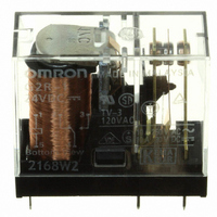
G2R-1-DC24
Description
RELAY PWR SPDT 10A 24VDC PCB
Manufacturer
Omron
Series
G2Rr
Datasheets
1.G2R-1A-E-DC12.pdf
(14 pages)
2.G2R-1A-E-DC12.pdf
(30 pages)
3.G2R-2-SND_DC24S.pdf
(19 pages)
4.G2R-1AE-DC24.pdf
(15 pages)
Specifications of G2R-1-DC24
Relay Type
General Purpose
Contact Form
SPDT (1 Form C)
Contact Rating (current)
10A
Switching Voltage
380VAC, 125VDC - Max
Coil Type
Standard
Coil Current
21.8mA
Coil Voltage
24VDC
Turn On Voltage (max)
16.8 VDC
Turn Off Voltage (min)
3.6 VDC
Mounting Type
Through Hole
Termination Style
PC Pin
Circuit
SPDT (1 Form C)
Contact Rating @ Voltage
10A @ 250VAC
Control On Voltage (max)
16.8 VDC
Control Off Voltage (min)
3.6 VDC
Coil Voltage Vdc Nom
24V
Contact Current Max
10A
Contact Voltage Ac Nom
250V
Contact Voltage Dc Nom
30V
Coil Resistance
1100ohm
Contact Configuration
SPDT
Current, Rating
10 A
Dielectric Rating
5000 VAC @ 50⁄60 Hz (For 1 Minute Between Coil and Contacts)
Dimensions
1.14 in. L x 0.51 in. W x 1.40 in. H
Function
Power
Number Of Pins
5
Power, Rating
2500⁄300 VA⁄W
Resistance, Coil
253 Ohms
Standards
UL, CSA, VDE, CE
Temperature, Operating, Maximum
70 °C
Temperature, Operating, Minimum
-40 °C
Termination
Through Hole
Voltage, Control
24 VDC
Voltage, Rating
380 VAC
Contact Rating
10 A
Contact Termination
Solder Pin
Mounting Style
Through Hole
Power Consumption
530 mW
Contact Material
Silver Alloy
Lead Free Status / RoHS Status
Lead free / RoHS Compliant
Lead Free Status / RoHS Status
Lead free / RoHS Compliant, Lead free / RoHS Compliant
Other names
G2R-1-DC24
G2R1DC24
Z2840
G2R1DC24
Z2840
Available stocks
Company
Part Number
Manufacturer
Quantity
Price
Company:

Part Number:
G2R-1-DC24V
Manufacturer:
OMRON
Quantity:
12 000
Company:
Part Number:
G2R-1-DC24V
Manufacturer:
NAIS
Quantity:
20 000
Part Number:
G2R-1-DC24V
Manufacturer:
OMRON欧姆龙进口
Quantity:
20 000


■ Conductor Width and Thickness
The following thickness of copper foil are standard: 35 μm and
70 μm. The conductor width is determined by the current flow and
allowable temperature rise. Refer to the chart below.
■ Conductor Pitch
The conductor pitch on a PCB is determined according to the insula-
tion resistance between conductors and the environmental condi-
tions under which the PCB is to be placed. The following graph
shows the general relationship between the voltage between conduc-
tors and the conductor pitch on a PCB. However, if the PCB must
conform to safety organization standards (such as UL, CSA, VDE,
etc.), priority must be given to fulfilling their requirements.
A = w/o coating at altitude of 3,000 m max.
B = w/o coating at altitude of 3,000 m
C = w/coating at altitude of 3,000 m max.
D = w/coating at altitude of 3,000 m or higher
Conductor Width and Carry Current
(according to IEC Pub326-3)
or higher but lower than 15,000 m
Voltage between Conductors vs.
Conductor Pitch
0.03 0.05 0.07 0.1
Conductor pitch (mm)
305 g/m
35 mm
0.3
2
610 g/m
70 mm
0.5 0.7
100°C
75°C
50°C
40°C
30°C
20°C
10°C
2
A
B
C
D
Sectional area
(mm )
Electromechanical Relays
2
■ Temperature and Humidity
PCBs expand or contract with changes in temperature. Should
expansion occur with a relay mounted on the PCB, the internal com-
ponents of the relay may be shifted out of operational tolerance. As a
result, the relay may not be able to operate with its normal character-
istics.
PCB materials have “directionality,” which means that a PCB gener-
ally has expansion and contraction coefficients 1/10 to 1/2 higher in
the vertical direction than in the horizontal direction. Conversely, its
warp in the vertical direction is 1/10 to 1/2 less than in the horizontal
direction. Therefore, take adequate counter-measures against
humidity by coating the PCB. Should heat or humidity be entirely too
high, the relay’s physical characteristics will likewise be affected. For
example, as the heat rises the PCB’s insulation resistance degrades.
Mechanically, PCB parts will continue to expand as heat is applied,
eventually passing the elastic limit, which will permanently warp com-
ponents.
Moreover, if the relay is used in an extremely humid environment, sil-
ver migration may take place.
■ Gas
Exposure to gases containing substances such as sulfuric acid, nitric
acid, or ammonia can cause malfunctions such as faulty contacting
in relays. They can also cause the copper film of a PCB to corrode, or
prevent positive contacts between the PCB’s connectors. Of the
gases mentioned, nitric acid is particularly damaging as it tends to
accelerate the silver migration. As a counter-measure against gas
exposure damage, the following processes on the relay and PCB
have proved useful.
■ Vibration and Shock
Although the PCB itself is not usually a source of vibration or shock, it
may simplify or prolong the vibration by sympathetically vibrating with
external vibrations or shocks. Securely fix the PCB, paying attention
to the following points.
Outer Casing,
housing
Relay
PCB, Copper Film
Connector
Rack Mounting
Screw Mounting
Mounting Method
Item
Technical Information
No gap between rack’s guide & PCB
Securely tighten screw. Place heavy compo-
nents such as relays on part of PCB near
screws.
Attach rubber washers to screws when mount-
ing components that are affected by shock
(such as audio devices.)
Sealed construction by using packing, etc.
Use of simplified hermetically sealed type re-
lay, DIP relay
Coating
Gold-plating, rhodium-plating process
Remarks
Process
17
Related parts for G2R-1-DC24
Image
Part Number
Description
Manufacturer
Datasheet
Request
R


Part Number:
Description:
RELAY PWR SPDT 10A 12VDC PCB
Manufacturer:
Omron
Datasheet:

Part Number:
Description:
RELAY PWR SPDT 16A 18VDC PCB
Manufacturer:
Omron
Datasheet:
Part Number:
Description:
RELAY PWR SPDT 16A 120VAC PCB
Manufacturer:
Omron
Datasheet:

Part Number:
Description:
RELAY PWR SPDT 10A 120VAC PCB
Manufacturer:
Omron
Datasheet:

Part Number:
Description:
RELAY SPDT 6VDC PLUG-IN W/LED
Manufacturer:
Omron
Datasheet:
Part Number:
Description:
RELAYS
Manufacturer:
Omron
Datasheet:
Part Number:
Description:
RELAY
Manufacturer:
Omron
Datasheet:
Part Number:
Description:
RELAY
Manufacturer:
Omron
Datasheet:

Part Number:
Description:
RELAY
Manufacturer:
Omron
Datasheet:
Part Number:
Description:
RELAY
Manufacturer:
Omron
Datasheet:
Part Number:
Description:
Relay
Manufacturer:
Omron
Datasheet:
Part Number:
Description:
RELAY
Manufacturer:
Omron
Datasheet:
Part Number:
Description:
RELAY
Manufacturer:
Omron
Datasheet: