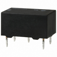
G6E-134P-ST-US-DC3 Omron, G6E-134P-ST-US-DC3 Datasheet

G6E-134P-ST-US-DC3
Specifications of G6E-134P-ST-US-DC3
G6E-134P-ST-USDC3
G6E134PSTUSDC3
Z2599
Available stocks
Related parts for G6E-134P-ST-US-DC3
G6E-134P-ST-US-DC3 Summary of contents
Page 1
... Refer to pages for details. Ordering Information Contact form Terminal SPDT Bifurcated Straight terminal crossbar Self-clinching termi- nal Note: When ordering, add the rated coil voltage to the model number. Example: G6E-134P-US 12 VDC Model Number Legend G6E - - Relay Function None: Single-side stable U: Single-winding latching ...
Page 2
... Set coil: Approx. 200 mW Reset coil: Approx. 200 mW Resistive load (cosφ 0 125 VAC VDC Ag (Au-Alloy 250 VAC, 220 VDC VA µ mVDC G6E 24 VDC 48 VDC 8.3 mA 8.3 mA 2,880 Ω 5,760 Ω 4.70 5.35 3.90 5.12 170% of rated voltage at 23° ...
Page 3
... Approved Standards ■ UL508 (File No. E41515)/CSA C22.2, No.14 (File No. LR31928) Contact form Coil ratings SPDT VDC 2 2 Contact ratings 0.2 A, 250 VAC (general use) 0.6 A, 125 VAC (general use VDC (resistive) 0.6 A, 125 VDC (resistive, Ag contact only) G6E 59 ...
Page 4
... Switching current (A) Note: The maximum coil voltage refers to the G6E Ambient Temperature vs. Maximum Coil Voltage G6E-134P-US G6EK-134P-US G6EU-134P-US G6E-134P-US Only at 48VDC Ambient temperature (°) maxi-mum value in a varying range of operating power voltage, not a continuous voltage. ...
Page 5
... All units are in millimeters unless otherwise indicated. 2. Orientation marks are indicated as follows: G6E-134P-US G6E-194P-US 16 max. (15.9) * 0.6 1.6 5.08 G6E-134C-US G6E-194C-US 16 max. (15.9) * 3.16 2.86 0.6 1.6 5.08 G6EU-134P-US G6EU-194P-US 16 max. (15.9) * 0.6 1.6 5.08 G6EU-134C-US G6EU-194C-US 16 max. (15.9) * 2.86 3.16 0.6 1.6 5.08 10 max. (9. max. 0.3 (7 ...
Page 6
... G6E G6EK-134P-US G6EK-194P-US 16 max. (15.9) * 0.6 1.6 5.08 G6EK-134C-US G6EK-194C-US 16 max. (15.9) * 2.86 3.16 0.6 1.6 5.08 Precautions Refer to page 25 for information on general precautions. Be sure to read these precautions before using the Relay. Precautions for Correct Use ■ Long-term Continuously ON Contacts Using the Relay in a circuit where the Relay will be ON continu- ...


