G6E-134P-ST-US-DC3 Omron, G6E-134P-ST-US-DC3 Datasheet - Page 6
G6E-134P-ST-US-DC3
Manufacturer Part Number
G6E-134P-ST-US-DC3
Description
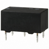
RELAY SPDT PCB 2A 3VDC
Manufacturer
Omron
Series
G6Er
Specifications of G6E-134P-ST-US-DC3
Coil Type
Standard
Coil Current
66.7mA
Relay Type
General Purpose
Circuit
SPDT (1 Form C)
Contact Rating @ Voltage
2A @ 30VDC
Coil Voltage
3VDC
Control On Voltage (max)
2.1 VDC
Control Off Voltage (min)
0.3 VDC
Mounting Type
Through Hole
Termination Style
PC Pin
Contact Configuration
SPDT
Contact Current Max
3A
Contact Voltage Ac Nom
125V
Contact Voltage Dc Nom
30V
Coil Voltage Vdc Nom
3V
Lead Free Status / RoHS Status
Lead free / RoHS Compliant
Other names
G6E-134P-ST-USDC3
G6E-134P-ST-USDC3
G6E134PSTUSDC3
Z2599
G6E-134P-ST-USDC3
G6E134PSTUSDC3
Z2599
Available stocks
Company
Part Number
Manufacturer
Quantity
Price

Part Number:
G6E-134P-ST-US-DC3
Manufacturer:
OMRON/欧姆龙
Quantity:
20 000


G6E
Precautions
Refer to page 25 for information on general precautions. Be sure to read these precautions before using the Relay.
■
Long-term Continuously ON Contacts
Using the Relay in a circuit where the Relay will be ON continu-
ously for long periods (without switching) can lead to unstable
contacts because the heat generated by the coil itself will affect
the insulation, causing a film to develop on the contact surfaces.
We recommend using a latching relay (magnetic-holding relay) in
this kind of circuit. If a single-side stable model must be used in
this kind of circuit, we recommend using a fail-safe circuit design
that provides protection against contact failure or coil burnout.
Installation
Do not reverse the polarity of the coil (+, -).
Provide sufficient space between Relays when mounting two or
more on the same PCB, as shown in the following diagram.
62
Cat. No. K024-E1-06
G6EK-134P-US
G6EK-194P-US
G6EK-134C-US
G6EK-194C-US
Precautions for Correct Use
Close
mounting
ALL DIMENSIONS SHOWN ARE IN MILLIMETERS.
To convert millimeters into inches, multiply by 0.03937. To convert grams into ounces, multiply by 0.03527.
3.16
Distance between terminals:
2.54 × 2 (pitch) max.
1.6
1.6
0.6
0.6
2.86
5.08
5.08
16 max.
(15.9) *
16 max.
(15.9) *
7.62
7.62
*Average value
*Average value
0.25
0.25
10 max.
(9.9) *
10 max.
(9.9) *
7.62
7.62
0.3
0.3
Wiring
Refer to the following diagram when wiring to switch a DC load.
The difference in polarity applied to the contacts will affect the
endurance of the Relay due to the amount of contact movement.
To extend the endurance characteristics beyond the performance
ratings, wire the common (pin 7) terminal to the positive (+) side.
Ultrasonic Cleaning
Do not use ultrasonic cleaning on standard relay models. Doing
so may result in resonance, coil burnout, and contact adhesion
within the Relay. Use a model designed for ultrasonic cleaning if
ultrasonic cleaning is required.
Relay Handling
When washing the product after soldering the Relay to a PCB,
use a water-based solvent or alcohol-based solvent, and keep the
solvent temperature to less than 40°C. Do not put the Relay in a
cold cleaning bath immediately after soldering.
3.5
8 max.
(7.9) *
8 max.
(7.9) *
+
−
Wiring Diagram
Six, 1.0-dia. holes
(1.65)
Load
Terminal Arrangement/
Internal Connections
(Bottom View)
12
Mounting Holes
(Bottom View)
Tolerance: ±0.1
7
+ 1
12
10
Load
5.08
S 3
10
-
7.62
R
+ 6
7
7.62
(1.19)
G6E
Related parts for G6E-134P-ST-US-DC3
Image
Part Number
Description
Manufacturer
Datasheet
Request
R

Part Number:
Description:
LOW SIGNAL RELAY
Manufacturer:
Omron
Datasheet:

Part Number:
Description:
Low Signal Relays - PCB 2A Relay PCB SPDT 3VDC
Manufacturer:
Omron
Datasheet:

Part Number:
Description:
SIGNAL RELAY, SPDT, 12VDC, 3A, THD
Manufacturer:
Omron
Datasheet:
Part Number:
Description:
SIGNAL RELAY, SPDT, 24VDC, 3A, THD
Manufacturer:
Omron
Datasheet:
Part Number:
Description:
LOW SIGNAL RELAY
Manufacturer:
Omron
Datasheet:
Part Number:
Description:
RELAY SPDT PCB 2A 24VDC
Manufacturer:
Omron
Datasheet:

Part Number:
Description:
LOW SIGNAL RELAY
Manufacturer:
Omron
Datasheet:
Part Number:
Description:
SIGNAL RELAY, SPDT, 12VDC, 3A, THD
Manufacturer:
Omron
Datasheet:
Part Number:
Description:
SIGNAL RELAY SPDT 5VDC, 3A, THROUGH HOLE
Manufacturer:
Omron
Datasheet:
Part Number:
Description:
LOW SIGNAL RELAY
Manufacturer:
Omron
Datasheet:
Part Number:
Description:
LOW SIGNAL RELAY
Manufacturer:
Omron
Datasheet:
Part Number:
Description:
Low Signal Relays - PCB LO SENS SPDT 24VDC
Manufacturer:
Omron
Datasheet:
Part Number:
Description:
LOW SIGNAL RELAY
Manufacturer:
Omron
Datasheet:
Part Number:
Description:
LOW SIGNAL RELAY
Manufacturer:
Omron
Datasheet:
Part Number:
Description:
LOW SIGNAL RELAY
Manufacturer:
Omron
Datasheet: