S108T02F Sharp Microelectronics, S108T02F Datasheet
S108T02F
Specifications of S108T02F


Related parts for S108T02F


S108T02F Summary of contents
Page 1
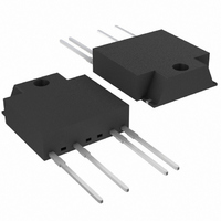
... S108T02 Series and S208T02 Series Solid State Relays (SSR) are an integration of an infrared emitting diode (IRED), a Phototriac Detector and a main output Triac. These devices are ideally suited for controlling high voltage AC loads with solid state reliability while providing 3.0kV isolation (V (rms) ) from input to out- iso put. ■ ...
Page 2
Internal Connection Diagram Zero Crossing Circuit ■ Outline Dimensions S108T02 ±0.2 23 ±0.2 7 Common to pin No.2 Common to pin No.2 ±0.2 ±0.2 6.4 φ 3.7 Epoxy resin ...
Page 3
Date code (2 digit) 1st digit Year of production A.D. A.D Mark Mark 1990 A 2002 P 1991 B 2003 R 1992 C 2004 S 1993 D 2005 T 1994 E 2006 U 1995 F 2007 V 1996 H 2008 ...
Page 4
Absolute Maximum Ratings Parameter Forward current Input Reverse voltage RMS ON-state current Peak one cycle surge current Repetitive S108T02 peak OFF-state voltage S208T02 Output Non-Repetitive S108T02 peak OFF-state voltage S208T02 Critical rate of rise of ON-state current Operating frequency ...
Page 5
... Model Line-up (1) (Lead-free terminal components) Sleeve Shipping Package 25pcs/sleeve S108T02F Model No. S208T02F ■ Model Line-up (2) (Lead solder plating components) Sleeve Shipping Package 25pcs/sleeve S108T02 Model No. S208T02 Please contact a local SHARP sales representative to see the actual status of the production. I [mA DRM ...
Page 6
Fig.1 Forward Current vs. Ambient Temperature − Ambient temperature T Fig.2 RMS ON-state Current vs. Ambient Temperature (3) ( ( ...
Page 7
Fig.5 Surge Current vs. Power-on Cycle 120 100 Power-on cycle (Times) Fig.7 Maximum ON-state Power Dissipation vs. RMS ON-state Current 10 T =25˚ ...
Page 8
Design Considerations ● Recommended Operating Conditions Parameter Input signal current at ON state Input Input signal current at OFF state S108T02 Load supply voltage S208T02 Output Load supply current Frequency Operating temperature ∗ See Fig.2 about derating ...
Page 9
Make sure there are no warps or bumps on the heat sink, insulation sheet and device surface. (b) Make sure there are no metal dusts or burrs attached onto the heat sink, insulation sheet and device sur- face. (c) ...
Page 10
Manufacturing Guidelines ● Soldering Method Flow Soldering (No solder bathing) Flow soldering should be completed below 260˚C and within 10s. Preheating is within the bounds of 100 to 150˚C and 30 to 80s. Please solder within one time. Other ...
Page 11
Cleaning instructions Solvent cleaning : Solvent temperature should be 45˚C or below. Immersion time should be 3minutes or less. Ultrasonic cleaning : The impact on the device varies depending on the size of the cleaning bath, ultrasonic output, cleaning ...
Page 12
Package specification ● Sleeve package Package materials Sleeve : HIPS Stopper : Olefine-Elastomer Package method MAX. 25pcs of products shall be packaged in a sleeve. Both ends shall be closed by stoppers. MAX. 20 sleeves in one case. Sleeve ...
Page 13
Important Notices · The circuit application examples in this publication are provided to explain representative applications of SHARP devices and are not intended to guarantee any circuit design or license any intellectual property rights. SHARP takes no responsibility for ...