H5CX-ASD-N-DC12-24/AC24 Omron, H5CX-ASD-N-DC12-24/AC24 Datasheet - Page 24
H5CX-ASD-N-DC12-24/AC24
Manufacturer Part Number
H5CX-ASD-N-DC12-24/AC24
Description
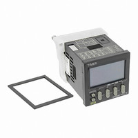
RELAY TIMER DGTL TRANS 12-24VDC
Manufacturer
Omron
Series
H5CXr
Specifications of H5CX-ASD-N-DC12-24/AC24
Relay Type
Integrated
Function
Programmable (Multi-Function)
Delay Time
0.001 Sec ~ 9999 Hrs
Output Type
Transistor
Voltage - Supply
12 ~ 24VDC, 24VAC
Mounting Type
Panel Mount
Termination Style
Screw Terminal
Timing Adjustment Method
DIP Switches
Timing Initiate Method
Input Voltage, Trigger Signal
Timing Range
0.001 s to 9999 Hrs
Supply Voltage
12 V to 24 V
Current Rating (max)
100 mA
Display Type
4 Digit LCD Backlight
Product
Digital Timer
Lead Free Status / RoHS Status
Lead free / RoHS Compliant
Circuit
-
Contact Rating @ Voltage
-
Lead Free Status / Rohs Status
Lead free / RoHS Compliant
Other names
H5CXASDNDC1224AC24
Z3001
Z3001


Z Mode
Output quantity can be adjusted by changing the cycle time set in the adjustment level to 1 and by changing the ON duty (%) set value.
The set value shows the ON duty (%) and can be set to a value between 0 and 100 (%). When the cycle time is 0, the output will always be OFF.
When the cycle time is not 0 and when ON duty has been set to 0 (%), the output will always be OFF. When ON duty has been set to 100 (%), the
output will always be ON.
Timing
diagram
Timing
diagram
Timing
diagram
Timing
diagram
Control output
Control output
Control output
Control output
Start signal
Start signal
ON duty setting
(%) ON time
ON duty setting
(%) ON time
Start signal
UP
DOWN
Set value
Set value
Start signal
Cycle time
Set value
Set value
Set value
Cycle time
Set value
UP
DOWN
UP
DOWN
UP
DOWN
Power
Reset
Power
Reset
Reset
Gate
Power
Reset
Power
Gate
Gate
Gate
0
0
0
0
0
0
0
0
Output mode F: Cumulative (Timer does not reset when power comes ON.)
Output mode d: Signal OFF delay (Timer resets when power comes ON.)
Output mode E: Interval (Timer resets when power comes ON.)
Z mode: ON/OFF-duty adjustable flicker
The control output is ON when the start signal is ON
(except when the power is OFF or the reset is ON).
The timer is reset when the time is up.
Start signal
input
*
**
Start signal
input
*
Start signal
input
*
**
*
**
Timing starts when the start signal goes ON.
The status of the control output is reversed
when time is up (ON at start).
While the start signal is ON, the timer starts when power
comes ON or when the reset input goes OFF.
Basic Operation
Start signal enables timing (timing is stopped when the
start signal is OFF or when the power is OFF).
A sustained control output is used.
Start signal
input
Output
Timing starts when the start signal comes ON.
The control output is reset when time is up.
While the start signal is ON, the timer starts when
power comes ON or when the reset input goes OFF.
Output
Output is instantaneous when setting is 0.
Power
Basic Operation
Power
Basic Operation
Output
Basic Operation
Output functions only during start signal input when
setting is 0.
Start signal input is enabled during timing.
Power
Output
Normal output operation will not be possible if the set
time is too short.
Set the value to at least 100 ms (contact output type).
Start signal input is disabled during timing.
Output is disabled when the setting is 0.
Start signal input is enabled during timing.
Power
**
**
**
Timing
ON duty (%)
Timing
Timing
(cycle time)
Timing
Sustained
Timing
Timing
ON duty (%)
Timing
(cycle time)
Timing
H5CX-A/-L
24
Related parts for H5CX-ASD-N-DC12-24/AC24
Image
Part Number
Description
Manufacturer
Datasheet
Request
R

Part Number:
Description:
Scrw Term,Trans OUT, Multi-Fnc
Manufacturer:
Omron

Part Number:
Description:
G6S-2GLow Signal Relay
Manufacturer:
Omron Corporation
Datasheet:
Part Number:
Description:
Compact, Low-cost, SSR Switching 5 to 20 A
Manufacturer:
Omron Corporation
Datasheet:
Part Number:
Description:
Manufacturer:
Omron Corporation
Datasheet:
Part Number:
Description:
Manufacturer:
Omron Corporation
Datasheet:
Part Number:
Description:
Manufacturer:
Omron Corporation
Datasheet:
Part Number:
Description:
Manufacturer:
Omron Corporation
Datasheet:
Part Number:
Description:
Manufacturer:
Omron Corporation
Datasheet:
Part Number:
Description:
Manufacturer:
Omron Corporation
Datasheet: