H5CX-ASD-N-DC12-24/AC24 Omron, H5CX-ASD-N-DC12-24/AC24 Datasheet - Page 30
H5CX-ASD-N-DC12-24/AC24
Manufacturer Part Number
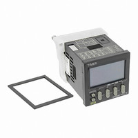
H5CX-ASD-N-DC12-24/AC24
Description
RELAY TIMER DGTL TRANS 12-24VDC
Manufacturer
Omron
Series
H5CXr
Specifications of H5CX-ASD-N-DC12-24/AC24
Relay Type
Integrated
Function
Programmable (Multi-Function)
Delay Time
0.001 Sec ~ 9999 Hrs
Output Type
Transistor
Voltage - Supply
12 ~ 24VDC, 24VAC
Mounting Type
Panel Mount
Termination Style
Screw Terminal
Timing Adjustment Method
DIP Switches
Timing Initiate Method
Input Voltage, Trigger Signal
Timing Range
0.001 s to 9999 Hrs
Supply Voltage
12 V to 24 V
Current Rating (max)
100 mA
Display Type
4 Digit LCD Backlight
Product
Digital Timer
Lead Free Status / RoHS Status
Lead free / RoHS Compliant
Circuit
-
Contact Rating @ Voltage
-
Lead Free Status / Rohs Status
Lead free / RoHS Compliant
Other names
H5CXASDNDC1224AC24
Z3001
Z3001


Timing Charts
Twin Timer Operation
The gate input is not included in the H5CX-L8@ models.
Self-diagnostic Function
The following displays will appear if an error occurs.
Note: This includes times when the life of the EEPROM has expired.
Sustained
Output
Sustained
Output
e1
e2
e2
Timing
diagram
Timing
diagram
Main display
Control output
Control output
Start signal
UP
DOWN
Start signal
UP
DOWN
OFF time
OFF time
ON time
ON time
OFF time
OFF time
ON time
ON time
Power
Reset
Reset
Gate
Power
Gate
0
0
0
0
Not lit
Not lit
sum
Sub-display
CPU
Memory error (RAM)
Memory error (EEP)
(See note)
Error
Output mode toff: Flicker OFF start
Output mode ton: Flicker ON start
OFF
OFF
OFF
Output status
Either press the reset key or reset the
power supply.
Reset the power supply.
Reset to the factory settings using
the reset key.
Correction method
Timing starts when the start signal goes ON.
The status of the control output is reversed when time
is up (OFF at start).
While the start signal is ON, the timer starts when the
power comes ON or when the reset input goes OFF.
Start signal
input
*
**
Timing starts when the start signal goes ON.
The status of the control output is reversed when time
is up (ON at start).
While the start signal is ON, the timer starts when the
power comes ON or when the reset input goes OFF.
Start signal
input
*
**
Output
Output
Basic Operation
Power
Basic Operation
Power
Normal output operation will not be possible if the
ON/OFF set time is too short.
Set the value to at least 100 ms (contact output
type).
Start signal input is disabled during timing.
Normal output operation will not be possible if the
ON/OFF set time is too short.
Set the value to at least 100 ms (contact output
type).
Start signal input is disabled during timing.
**
**
Timing
OFF
Timing
ON
Timing
OFF
Timing
ON
H5CX-A/-L
No change
No change
0
Timing
OFF
Timing
ON
Set value after
reset
Timing
OFF
Timing
ON
30
Related parts for H5CX-ASD-N-DC12-24/AC24
Image
Part Number
Description
Manufacturer
Datasheet
Request
R

Part Number:
Description:
Scrw Term,Trans OUT, Multi-Fnc
Manufacturer:
Omron

Part Number:
Description:
G6S-2GLow Signal Relay
Manufacturer:
Omron Corporation
Datasheet:
Part Number:
Description:
Compact, Low-cost, SSR Switching 5 to 20 A
Manufacturer:
Omron Corporation
Datasheet:
Part Number:
Description:
Manufacturer:
Omron Corporation
Datasheet:
Part Number:
Description:
Manufacturer:
Omron Corporation
Datasheet:
Part Number:
Description:
Manufacturer:
Omron Corporation
Datasheet:
Part Number:
Description:
Manufacturer:
Omron Corporation
Datasheet:
Part Number:
Description:
Manufacturer:
Omron Corporation
Datasheet:
Part Number:
Description:
Manufacturer:
Omron Corporation
Datasheet: