ST203C107MAJ05 AVX Corporation, ST203C107MAJ05 Datasheet - Page 79
ST203C107MAJ05
Manufacturer Part Number
ST203C107MAJ05
Description
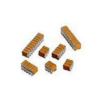
CAP CER 100UF 25V STACKED SMD
Manufacturer
AVX Corporation
Series
TurboCap™r
Specifications of ST203C107MAJ05
Capacitance
100µF
Tolerance
±20%
Temperature Coefficient
X7R
Voltage - Rated
25V
Mounting Type
Surface Mount, MLCC
Operating Temperature
-55°C ~ 125°C
Features
Stacked
Applications
Filtering Switch Mode Power Supplies
Package / Case
10-Stacked SMD, J-Lead
Size / Dimension
0.525" L x 0.300" W (13.34mm x 7.62mm)
Thickness
5.59mm Max
Lead Style
J-Lead
Voltage Rating
25 Volts
Operating Temperature Range
- 55 C to + 125 C
Product
General Type MLCCs
Dielectric Characteristic
X7R
Capacitance Tolerance
± 20%
Capacitor Case Style
DIP
No. Of Pins
10
Capacitor Mounting
SMD
Rohs Compliant
No
Termination Style
Radial
Lead Spacing
6.35 mm
Dimensions
7.62 mm W x 13.34 mm L x 5.59 mm H
Dissipation Factor Df
2.5
Lead Free Status / RoHS Status
Contains lead / RoHS non-compliant
Ratings
-
Lead Spacing
-
Lead Free Status / RoHS Status
Contains lead / RoHS non-compliant
Other names
478-6116


General Description
Table 1: EIA and MIL Temperature Stable and General
In specifying capacitance change with temperature for Class
2 materials, EIA expresses the capacitance change over an
operating temperature range by a 3 symbol code. The
first symbol represents the cold temperature end of the
temperature range, the second represents the upper limit of
the operating temperature range and the third symbol repre-
sents the capacitance change allowed over the operating
temperature range. Table 1 provides a detailed explanation of
the EIA system.
78
EXAMPLE – A capacitor is desired with the capacitance value at 25°C
to increase no more than 7.5% or decrease no more than 7.5% from
-30°C to +85°C. EIA Code will be Y5F.
Temperature characteristic is specified by combining range and change
symbols, for example BR or AW. Specification slash sheets indicate the
characteristic applicable to a given style of capacitor.
Symbol
Symbol
RS198
Code
A
B
C
Perc ent Capacity Change Over Temperature Range
W
Q
R
X
Y
Z
Application Codes
X7
X5
Y5
Z5
D
P
R
S
U
E
F
T
V
Cap. Change
+15%, -15%
+15%, -15%
+22%, -56%
+15%, -15%
+30%, -70%
+20%, -20%
Zero Volts
Temperature Range
Percent Capacity Change
MIL CODE
EIA CODE
-55°C to +85°C
-55°C to +125°C
-55°C to +150°C
Temperature Range
-55°C to +125°C
+10°C to +85°C
-55°C to +85°C
-30°C to +85°C
+22%, - 56%
+22%, -33%
+22%, -82%
±3.3%
±4.7%
±7.5%
±10%
±15%
±22%
Cap. Change
+15%, -50%
+15%, -40%
+22%, -66%
+15%, -25%
+30%, -80%
+20%, -30%
Rated Volts
Effects of Voltage – Variations in voltage have little effect
on Class 1 dielectric but does affect the capacitance and
dissipation factor of Class 2 dielectrics. The application of
DC voltage reduces both the capacitance and dissipation
factor while the application of an AC voltage within a
reasonable range tends to increase both capacitance and
dissipation factor readings. If a high enough AC voltage is
applied, eventually it will reduce capacitance just as a DC
voltage will. Figure 2 shows the effects of AC voltage.
Capacitor specifications specify the AC voltage at which to
measure (normally 0.5 or 1 VAC) and application of the
wrong voltage can cause spurious readings.
+10
+20
-10
-20
-30
50
40
30
20
10
0
-55 -35
0
Typical Cap. Change vs. Temperature
Cap. Change vs. A.C. Volts
Temperature Degrees Centigrade
-15
12.5
+5
Volts AC at 1.0 KHz
Figure 2
Figure 3
X7R
X7R
+25 +45 +65 +85 +105 +125
0VDC
25
37.5
50
Related parts for ST203C107MAJ05
Image
Part Number
Description
Manufacturer
Datasheet
Request
R

Part Number:
Description:
Inverter Grade Thyristors
Manufacturer:
International Rectifier Corp.
Datasheet:

Part Number:
Description:
Manufacturer:
AVX Corporation
Datasheet:
Part Number:
Description:
Manufacturer:
AVX Corporation
Datasheet:
Part Number:
Description:
Manufacturer:
AVX Corporation
Datasheet:
Part Number:
Description:
Manufacturer:
AVX Corporation
Datasheet: