ST203C107MAJ05 AVX Corporation, ST203C107MAJ05 Datasheet - Page 81
ST203C107MAJ05
Manufacturer Part Number
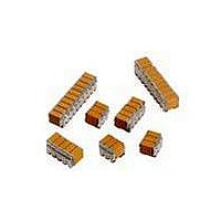
ST203C107MAJ05
Description
CAP CER 100UF 25V STACKED SMD
Manufacturer
AVX Corporation
Series
TurboCap™r
Specifications of ST203C107MAJ05
Capacitance
100µF
Tolerance
±20%
Temperature Coefficient
X7R
Voltage - Rated
25V
Mounting Type
Surface Mount, MLCC
Operating Temperature
-55°C ~ 125°C
Features
Stacked
Applications
Filtering Switch Mode Power Supplies
Package / Case
10-Stacked SMD, J-Lead
Size / Dimension
0.525" L x 0.300" W (13.34mm x 7.62mm)
Thickness
5.59mm Max
Lead Style
J-Lead
Voltage Rating
25 Volts
Operating Temperature Range
- 55 C to + 125 C
Product
General Type MLCCs
Dielectric Characteristic
X7R
Capacitance Tolerance
± 20%
Capacitor Case Style
DIP
No. Of Pins
10
Capacitor Mounting
SMD
Rohs Compliant
No
Termination Style
Radial
Lead Spacing
6.35 mm
Dimensions
7.62 mm W x 13.34 mm L x 5.59 mm H
Dissipation Factor Df
2.5
Lead Free Status / RoHS Status
Contains lead / RoHS non-compliant
Ratings
-
Lead Spacing
-
Lead Free Status / RoHS Status
Contains lead / RoHS non-compliant
Other names
478-6116


General Description
A capacitor is a component which is capable of storing
electrical energy. It consists of two conductive plates (elec-
trodes) separated by insulating material which is called the
dielectric. A typical formula for determining capacitance is:
Capacitance – The standard unit of capacitance is the
farad. A capacitor has a capacitance of 1 farad when 1
coulomb charges it to 1 volt. One farad is a very large unit
and most capacitors have values in the micro (10
(10
Dielectric Constant – In the formula for capacitance given
above the dielectric constant of a vacuum is arbitrarily cho-
sen as the number 1. Dielectric constants of other materials
are then compared to the dielectric constant of a vacuum.
Dielectric Thickness – Capacitance is indirectly propor-
tional to the separation between electrodes. Lower voltage
requirements mean thinner dielectrics and greater capaci-
tance per volume.
Area – Capacitance is directly proportional to the area of the
electrodes. Since the other variables in the equation are
usually set by the performance desired, area is the easiest
parameter to modify to obtain a specific capacitance within
a material group.
Energy Stored – The energy which can be stored in a
capacitor is given by the formula:
Potential Change – A capacitor is a reactive component
which reacts against a change in potential across it. This is
shown by the equation for the linear charge of a capacitor:
where
Thus an infinite current would be required to instantly
change the potential across a capacitor. The amount of
current a capacitor can “sink” is determined by the above
equation.
80
.224 = conversion constant
-9
) or pico (10
dV/dt = Slope of voltage transition across capacitor
C = capacitance (picofarads)
K = dielectric constant (Vacuum = 1)
A = area in square inches
t = separation between the plates in inches
C = Capacitance
E = energy in joules (watts-sec)
V = applied voltage
C = capacitance in farads
(thickness of dielectric)
(.0884 for metric system in cm)
I = Current
-12
) farad level.
I
ideal
C = .224 KA
E =
= C dV
1
dt
⁄
2
CV
t
2
-6
), nano
Equivalent Circuit – A capacitor, as a practical device,
exhibits not only capacitance but also resistance and
inductance. A simplified schematic for the equivalent circuit is:
Reactance – Since the insulation resistance (R
normally very high, the total impedance of a capacitor is:
where
The variation of a capacitor’s impedance with frequency
determines its effectiveness in many applications.
Phase Angle – Power Factor and Dissipation Factor are
often confused since they are both measures of the loss in
a capacitor under AC application and are often almost iden-
tical in value. In a “perfect” capacitor the current in the
capacitor will lead the voltage by 90°.
In practice the current leads the voltage by some other
phase angle due to the series resistance R
ment of this angle is called the loss angle and:
for small values of
which has led to the common interchangeability of the two
terms in the industry.
R
C = Capacitance
s
= Series Resistance
X
R
X
Z = Total Impedance
C
L
Z =
s
Loss
Angle
L
Power Factor (P.F.) = Cos
Dissipation Factor (D.F.) = tan
= Series Resistance
= Capacitive Reactance =
= Inductive Reactance
I (Ideal)
R
2
S
+ (X
the tan and sine are essentially equal
IR
C
I (Actual)
- X
f
R
s
S
L
)
2
R
Phase
Angle
L = Inductance
p
f
= Parallel Resistance
= 2 π fL
or Sine
2 π fC
1
R
C
S
. The comple-
P
V
p
) is
Related parts for ST203C107MAJ05
Image
Part Number
Description
Manufacturer
Datasheet
Request
R

Part Number:
Description:
Inverter Grade Thyristors
Manufacturer:
International Rectifier Corp.
Datasheet:

Part Number:
Description:
Manufacturer:
AVX Corporation
Datasheet:
Part Number:
Description:
Manufacturer:
AVX Corporation
Datasheet:
Part Number:
Description:
Manufacturer:
AVX Corporation
Datasheet:
Part Number:
Description:
Manufacturer:
AVX Corporation
Datasheet: