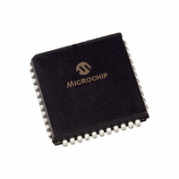
PIC18F442-I/L Microchip Technology, PIC18F442-I/L Datasheet - Page 3

PIC18F442-I/L
Manufacturer Part Number
PIC18F442-I/L
Description
IC MCU FLASH 8KX16 EE A/D 44PLCC
Manufacturer
Microchip Technology
Series
PIC® 18Fr
Datasheets
1.PIC16F616T-ISL.pdf
(8 pages)
2.PIC18F242-ISO.pdf
(332 pages)
3.PIC18F242-ISO.pdf
(14 pages)
4.PIC18F242-ISO.pdf
(16 pages)
5.PIC18F242-ISO.pdf
(16 pages)
6.PIC18F242-ISO.pdf
(14 pages)
7.PIC18LF242-ISO.pdf
(36 pages)
Specifications of PIC18F442-I/L
Core Size
8-Bit
Program Memory Size
16KB (8K x 16)
Core Processor
PIC
Speed
40MHz
Connectivity
I²C, SPI, UART/USART
Peripherals
Brown-out Detect/Reset, LVD, POR, PWM, WDT
Number Of I /o
34
Program Memory Type
FLASH
Eeprom Size
256 x 8
Ram Size
768 x 8
Voltage - Supply (vcc/vdd)
4.2 V ~ 5.5 V
Data Converters
A/D 8x10b
Oscillator Type
External
Operating Temperature
-40°C ~ 85°C
Package / Case
44-PLCC
Controller Family/series
PIC18
No. Of I/o's
34
Eeprom Memory Size
256Byte
Ram Memory Size
768Byte
Cpu Speed
40MHz
No. Of Timers
4
Processor Series
PIC18F
Core
PIC
Data Bus Width
8 bit
Data Ram Size
768 B
Interface Type
MSSP, SPI, I2C, PSP, USART
Maximum Clock Frequency
40 MHz
Number Of Programmable I/os
34
Number Of Timers
1 x 16 bit
Operating Supply Voltage
2 V to 5.5 V
Maximum Operating Temperature
+ 85 C
Mounting Style
SMD/SMT
3rd Party Development Tools
52715-96, 52716-328, 52717-734, 52712-325, EWPIC18
Development Tools By Supplier
PG164130, DV164035, DV244005, DV164005, PG164120, ICE2000, ICE4000, DM163022, DV164136
Minimum Operating Temperature
- 40 C
On-chip Adc
8
Package
44PLCC
Device Core
PIC
Family Name
PIC18
Maximum Speed
40 MHz
Lead Free Status / RoHS Status
Lead free / RoHS Compliant
For Use With
AC164309 - MODULE SKT FOR PM3 44PLCCXLT44L2 - SOCKET TRAN ICE 44PLCC444-1001 - DEMO BOARD FOR PICMICRO MCUDVA16XL441 - ADAPTER DEVICE ICE 44PLCCDV007003 - PROGRAMMER UNIVERSAL PROMATE II
Lead Free Status / Rohs Status
Details
Other names
PIC18F442I/L
Available stocks
Company
Part Number
Manufacturer
Quantity
Price
Company:
Part Number:
PIC18F442-I/L
Manufacturer:
Microchip Technology
Quantity:
10 000
1. Asynchronous Counter
EXAMPLE 1:
2010 Microchip Technology Inc.
Update:
Critical Timing of code sequence for instructions following last write to TMR1L or TMR1H.
When Timer1 is started or updated, the timer
needs to see a falling edge from the external clock
source before a rising edge can increment the
counter. If writes to TMR1H and TMR1L are not
completed while the external clock pulse is still
high, Timer1 will miss counting the first clock pulse
after the update.
When using an external crystal, the pulse width
from rising to falling edge is temperature depen-
dent and may decrease with temperature. As a
result, the timer may require an additional oscilla-
tion to overflow.
Code examples are given for the affected devices:
• PIC12/14/16/17 devices – Example 1 and
• PIC18 devices – Example 3
Both examples include code to wait for Timer1 to
increment twice between the RTCisr and Update
labels.
BTFSC
GOTO
BTFSS
GOTO
BCF
BSF
BCF
BSF
BSF
Example 2
TMR1L,0
$-1
TMR1L,0
$-1
T1CON,TMR1CS
TMR1H,7
T1CON,TMR1ON
T1CON,TMR1C
T1CON,TMR1ON
PIC12/14/16/17 CODE EXAMPLE FOR 1 SECOND OVERFLOW PERIOD WITH 32.786
kHZ OSCILLATOR
;Timer has just incremented, 31 μs before next rising edge to
;complete reload
;Select system clock for Timer1
;Timer1 high byte 0x80
;Timer1 off
;Select external crystal
;Timer1 on
In PIC18 devices, it is not possible to reliably
update Timer1 in a low-priority interrupt. A high-
priority interrupt could occur at any time and
unexpectedly delay the TMR1 update.
PIC18 devices also include Timer3 which is
functionally identical to Timer1.
Work around
Switching Timer1 to the main system oscillator
after reloading, the timer ensures the timer will see
a falling edge before switching back to the external
clock source.
Due to the time from Timer1 overflow to the reload
being application specific, wait for the timer to
increment before beginning the reload sequence.
This ensures the timer does not miss a rising edge
during reload. The timing of the clock source
changing is critical and is detailed in Example 1
and Example 2.
TIMER1 MODULE
DS80329B-page 3


