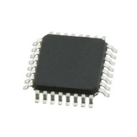
C8051F541-IQ Silicon Laboratories Inc, C8051F541-IQ Datasheet - Page 4

C8051F541-IQ
Manufacturer Part Number
C8051F541-IQ
Description
IC 8051 MCU 16K FLASH 32-QFP
Manufacturer
Silicon Laboratories Inc
Series
C8051F54xr
Specifications of C8051F541-IQ
Program Memory Type
FLASH
Program Memory Size
16KB (16K x 8)
Package / Case
32-QFP
Mfg Application Notes
LIN Bootloader AppNote
Core Processor
8051
Core Size
8-Bit
Speed
50MHz
Connectivity
SMBus (2-Wire/I²C), SPI, UART/USART
Peripherals
POR, PWM, Temp Sensor, WDT
Number Of I /o
25
Ram Size
1.25K x 8
Voltage - Supply (vcc/vdd)
1.8 V ~ 5.25 V
Data Converters
A/D 25x12b
Oscillator Type
Internal
Operating Temperature
-40°C ~ 125°C
Processor Series
C8051F5x
Core
8051
Data Bus Width
8 bit
Data Ram Size
256 B
Maximum Clock Frequency
50 MHz
Number Of Programmable I/os
25
Operating Supply Voltage
1.8 V to 5.25 V
Maximum Operating Temperature
+ 125 C
Mounting Style
SMD/SMT
3rd Party Development Tools
PK51, CA51, A51, ULINK2
Development Tools By Supplier
C8051F540DK
Minimum Operating Temperature
- 40 C
Lead Free Status / RoHS Status
Lead free / RoHS Compliant
For Use With
336-1672 - BOARD PROTOTYPE W/C8051F540336-1669 - KIT DEVELOPMENT FOR C8051F540
Eeprom Size
-
Lead Free Status / Rohs Status
Lead free / RoHS Compliant
Other names
336-1674
Available stocks
Company
Part Number
Manufacturer
Quantity
Price
Company:
Part Number:
C8051F541-IQ
Manufacturer:
Silicon Laboratories Inc
Quantity:
10 000
Company:
Part Number:
C8051F541-IQR
Manufacturer:
Silicon Laboratories Inc
Quantity:
10 000
C8051F54x
15. Power Management Modes................................................................................. 126
16. Reset Sources ...................................................................................................... 129
17. Oscillators and Clock Selection ......................................................................... 135
18. Port Input/Output ................................................................................................. 147
19. Local Interconnect Network (LIN)....................................................................... 170
20. SMBus................................................................................................................... 187
21. UART0 ................................................................................................................... 205
22. Enhanced Serial Peripheral Interface (SPI0) ..................................................... 214
4
15.1. Idle Mode....................................................................................................... 126
15.2. Stop Mode ..................................................................................................... 127
15.3. Suspend Mode .............................................................................................. 127
16.1. Power-On Reset ............................................................................................ 130
16.2. Power-Fail Reset/VDD Monitor ..................................................................... 130
16.3. External Reset ............................................................................................... 132
16.4. Missing Clock Detector Reset ....................................................................... 132
16.5. Comparator0 Reset ....................................................................................... 133
16.6. PCA Watchdog Timer Reset ......................................................................... 133
16.7. Flash Error Reset .......................................................................................... 133
16.8. Software Reset .............................................................................................. 133
17.1. System Clock Selection................................................................................. 135
17.2. Programmable Internal Oscillator .................................................................. 137
17.3. Clock Multiplier .............................................................................................. 140
17.4. External Oscillator Drive Circuit..................................................................... 142
18.1. Port I/O Modes of Operation.......................................................................... 148
18.2. Assigning Port I/O Pins to Analog and Digital Functions............................... 149
18.3. Priority Crossbar Decoder ............................................................................. 150
18.4. Port I/O Initialization ...................................................................................... 152
18.5. Port Match ..................................................................................................... 157
18.6. Special Function Registers for Accessing and Configuring Port I/O ............. 161
19.1. Software Interface with the LIN Controller..................................................... 171
19.2. LIN Interface Setup and Operation................................................................ 171
19.3. LIN Master Mode Operation .......................................................................... 174
19.4. LIN Slave Mode Operation ............................................................................ 175
19.5. Sleep Mode and Wake-Up ............................................................................ 176
19.6. Error Detection and Handling ........................................................................ 176
19.7. LIN Registers................................................................................................. 177
20.1. Supporting Documents .................................................................................. 188
20.2. SMBus Configuration..................................................................................... 188
20.3. SMBus Operation .......................................................................................... 188
20.4. Using the SMBus........................................................................................... 190
20.5. SMBus Transfer Modes................................................................................. 197
20.6. SMBus Status Decoding................................................................................ 201
21.1. Baud Rate Generator .................................................................................... 205
21.2. Data Format................................................................................................... 207
21.3. Configuration and Operation ......................................................................... 208
Rev. 1.1


