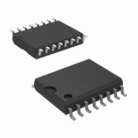
COP8SAA716M8/NOPB National Semiconductor, COP8SAA716M8/NOPB Datasheet - Page 42

COP8SAA716M8/NOPB
Manufacturer Part Number
COP8SAA716M8/NOPB
Description
IC MCU OTP 8BIT 1K 16-SOIC
Manufacturer
National Semiconductor
Series
COP8™ 8SAr
Datasheet
1.COP8-PGMA-28CSP.pdf
(60 pages)
Specifications of COP8SAA716M8/NOPB
Core Processor
COP8
Core Size
8-Bit
Speed
10MHz
Connectivity
Microwire/Plus (SPI)
Peripherals
POR, PWM, WDT
Number Of I /o
12
Program Memory Size
1KB (1K x 8)
Program Memory Type
OTP
Ram Size
64 x 8
Voltage - Supply (vcc/vdd)
2.7 V ~ 5.5 V
Oscillator Type
Internal
Operating Temperature
-40°C ~ 85°C
Package / Case
16-SOIC (0.300", 7.5mm Width)
Package
16SOIC W
Family Name
COP8
Maximum Speed
10 MHz
Operating Supply Voltage
3.3|5 V
Data Bus Width
8 Bit
Interface Type
SPI
Number Of Timers
1
Maximum Clock Frequency
10 MHz
Data Ram Size
64 B
Number Of Programmable I/os
16
Height
2.3 mm
Length
10.5 mm
Maximum Operating Temperature
+ 85 C
Minimum Operating Temperature
- 40 C
Supply Voltage (max)
5.5 V
Supply Voltage (min)
2.7 V
Width
7.6 mm
Lead Free Status / RoHS Status
Lead free / RoHS Compliant
Eeprom Size
-
Data Converters
-
Lead Free Status / Rohs Status
Details
Other names
*COP8SAA716M8
*COP8SAA716M8/NOPB
COP8SAA716M8
*COP8SAA716M8/NOPB
COP8SAA716M8
Available stocks
Company
Part Number
Manufacturer
Quantity
Price
Company:
Part Number:
COP8SAA716M8/NOPB
Manufacturer:
ADI
Quantity:
51
www.national.com
13.0 Instruction Set
Jump Indirect. In this 1-byte instruction, the lower byte of
the jump address is obtained from a table stored in program
memory, with the Accumulator serving as the low order byte
of a pointer into program memory. For purposes of access-
ing program memory, the contents of the Accumulator are
written to PCL (temporarily). The data pointed to by the
Program Counter (PCH/PCL) is loaded into PCL, while PCH
remains unchanged.
Example: Jump Indirect
The VIS instruction is a special case of the Indirect Transfer
of Control addressing mode, where the double-byte vector
associated with the interrupt is transferred from adjacent
addresses in program memory into the Program Counter in
order to jump to the associated interrupt service routine.
13.4 INSTRUCTION TYPES
The instruction set contains a wide variety of instructions.
The available instructions are listed below, organized into
related groups.
Some instructions test a condition and skip the next instruc-
tion if the condition is not true. Skipped instructions are
executed as no-operation (NOP) instructions.
13.4.1 Arithmetic Instructions
The arithmetic instructions perform binary arithmetic such as
addition and subtraction, with or without the Carry bit.
13.4.2 Transfer-of-Control Instructions
The transfer-of-control instructions change the usual se-
quential program flow by altering the contents of the Pro-
gram Counter. The Jump to Subroutine instructions save the
Program Counter contents on the stack before jumping; the
Return instructions pop the top of the stack back into the
Program Counter.
Add (ADD)
Add with Carry (ADC)
Subtract (SUB)
Subtract with Carry (SUBC)
Increment (INC)
Decrement (DEC)
Decimal Correct (DCOR)
Clear Accumulator (CLR)
Set Carry (SC)
Reset Carry (RC)
Jump Relative (JP)
Jump Absolute (JMP)
Jump Absolute Long (JMPL)
Jump Indirect (JID)
Jump to Subroutine (JSR)
JID
Accumulator
0126 Hex
Memory
Location
Memory
Reg/
PCU
PCL
(Continued)
Contents
C4 Hex
Before
01 Hex
26 Hex
32 Hex
Contents
01 Hex
32 Hex
26 Hex
32 Hex
After
42
13.4.3 Load and Exchange Instructions
The load and exchange instructions write byte values in
registers or memory. The addressing mode determines the
source of the data.
13.4.4 Logical Instructions
The logical instructions perform the operations AND, OR,
and XOR (Exclusive OR). Other logical operations can be
performed by combining these basic operations. For ex-
ample, complementing is accomplished by exclusiveORing
the Accumulator with FF Hex.
13.4.5 Accumulator Bit Manipulation Instructions
The Accumulator bit manipulation instructions allow the user
to shift the Accumulator bits and to swap its two nibbles.
13.4.6 Stack Control Instructions
13.4.7 Memory Bit Manipulation Instructions
set and reset individual bits in memory.
13.4.8 Conditional Instructions
The conditional instruction test a condition. If the condition is
true, the next instruction is executed in the normal manner; if
the condition is false, the next instruction is skipped.
Jump to Subroutine Long (JSRL)
Return from Subroutine (RET)
Return from Subroutine and Skip (RETSK)
Return from Interrupt (RETI)
Software Trap Interrupt (INTR)
Vector Interrupt Select (VIS)
Load (LD)
Load Accumulator Indirect (LAID)
Exchange (X)
Logical AND (AND)
Logical OR (OR)
Exclusive OR (XOR)
Rotate Right Through Carry (RRC)
Rotate Left Through Carry (RLC)
Swap Nibbles of Accumulator (SWAP)
Push Data onto Stack (PUSH)
Pop Data off of Stack (POP)
The memory bit manipulation instructions allow the user to
Set Bit (SBIT)
Reset Bit (RBIT)
Reset Pending Bit (RPND)
If Equal (IFEQ)
If Not Equal (IFNE)
If Greater Than (IFGT)
If Carry (IFC)
If Not Carry (IFNC)
If Bit (IFBIT)
If B Pointer Not Equal (IFBNE)
And Skip if Zero (ANDSZ)
Decrement Register and Skip if Zero (DRSZ)


