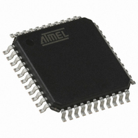
AT89C51CC01UA-RLRUM Atmel, AT89C51CC01UA-RLRUM Datasheet - Page 162

AT89C51CC01UA-RLRUM
Manufacturer Part Number
AT89C51CC01UA-RLRUM
Description
IC 8051 MCU 32K FLASH 44-VQFP
Manufacturer
Atmel
Series
AT89C CANr
Datasheet
1.T89C51CC01CA-7CTIM.pdf
(167 pages)
Specifications of AT89C51CC01UA-RLRUM
Core Processor
8051
Core Size
8-Bit
Speed
40MHz
Connectivity
CAN, UART/USART
Peripherals
POR, PWM, WDT
Number Of I /o
34
Program Memory Size
32KB (32K x 8)
Program Memory Type
FLASH
Eeprom Size
2K x 8
Ram Size
1.25K x 8
Voltage - Supply (vcc/vdd)
3 V ~ 5.5 V
Data Converters
A/D 8x10b
Oscillator Type
External
Operating Temperature
-40°C ~ 85°C
Package / Case
44-TQFP, 44-VQFP
Processor Series
AT89x
Core
8051
Data Bus Width
8 bit
Data Ram Size
1280 B
Interface Type
UART
Maximum Clock Frequency
40 MHz
Number Of Programmable I/os
34
Number Of Timers
2
Operating Supply Voltage
3 V to 5.5 V
Mounting Style
SMD/SMT
3rd Party Development Tools
PK51, CA51, A51, ULINK2
Development Tools By Supplier
CANADAPT28
For Use With
AT89OCD-01 - USB EMULATOR FOR AT8XC51 MCU
Lead Free Status / RoHS Status
Lead free / RoHS Compliant
Other names
AT89C51CC01UA-RLRUMTR
Available stocks
Company
Part Number
Manufacturer
Quantity
Price
- Current page: 162 of 167
- Download datasheet (2Mb)
Datasheet Change
Log for T89C51CC01
Changes from 4129F -
11/02 to 4129G - 04/03
Changes from 4129G -
04/03 to 4129H - 10/03
Changes from 4129H -
10/03 to 4129I - 12/03
Changes from 4129I -
12/03 to 4129J - 08/04
Changes from 4129J -
08/04 to 4129K 01/05
Changes from 4129K
01/05 to 4129L 08/05
Changes from 4129L
08/05 to 4129M 02/08
Changes from 4129M
02/08 to 4129N 03/08
162
A/T89C51CC01
1. Changed the endurance of Flash to 100, 000 Write/Erase cycles.
2. Added note on Flash retention formula for V
1. Updated “Electrical Characteristics” on page 144.
2. Corrected Figure 46 on page 84.
1. Correction in Registers CPA and CPS0.
2. Added note regarding PSEN during power On see Section “Hardware Boot Pro-
1. Figure clock-out mode modified see, Figure 37 on page 67.
2. Added explanation on the CAN protocol, see Section “CAN Controller”, page 75.
3. Corrected error in Table 53 on page 72, (1.25ms to 1.25s) for Time-out
1. Minor corrections throughout the document.
2. Clarification to Mode Switching Waveforms diagram. See page 16.
1. Added green product ordering information.
1. Removed non-green packages from ordering information.
1. Removed CA-BGA package offering from ordering information.
2. Updated package drawings.
Standard Voltage", page 144.
cess”, page 48.
Computation.
IH1
, in Section "DC Parameters for
4129N–CAN–03/08
Related parts for AT89C51CC01UA-RLRUM
Image
Part Number
Description
Manufacturer
Datasheet
Request
R

Part Number:
Description:
Manufacturer:
Atmel Corporation
Datasheet:

Part Number:
Description:
DEV KIT FOR AVR/AVR32
Manufacturer:
Atmel
Datasheet:

Part Number:
Description:
INTERVAL AND WIPE/WASH WIPER CONTROL IC WITH DELAY
Manufacturer:
ATMEL Corporation
Datasheet:

Part Number:
Description:
Low-Voltage Voice-Switched IC for Hands-Free Operation
Manufacturer:
ATMEL Corporation
Datasheet:

Part Number:
Description:
MONOLITHIC INTEGRATED FEATUREPHONE CIRCUIT
Manufacturer:
ATMEL Corporation
Datasheet:

Part Number:
Description:
AM-FM Receiver IC U4255BM-M
Manufacturer:
ATMEL Corporation
Datasheet:

Part Number:
Description:
Monolithic Integrated Feature Phone Circuit
Manufacturer:
ATMEL Corporation
Datasheet:

Part Number:
Description:
Multistandard Video-IF and Quasi Parallel Sound Processing
Manufacturer:
ATMEL Corporation
Datasheet:

Part Number:
Description:
High-performance EE PLD
Manufacturer:
ATMEL Corporation
Datasheet:

Part Number:
Description:
8-bit Flash Microcontroller
Manufacturer:
ATMEL Corporation
Datasheet:

Part Number:
Description:
2-Wire Serial EEPROM
Manufacturer:
ATMEL Corporation
Datasheet:


