PIC16CE624/JW Microchip Technology, PIC16CE624/JW Datasheet - Page 91
PIC16CE624/JW
Manufacturer Part Number
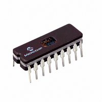
PIC16CE624/JW
Description
IC MCU EPROM1KX14 EE COMP 18CDIP
Manufacturer
Microchip Technology
Series
PIC® 16Cr
Datasheet
1.PIC16CE623-04P.pdf
(113 pages)
Specifications of PIC16CE624/JW
Core Processor
PIC
Core Size
8-Bit
Speed
20MHz
Peripherals
Brown-out Detect/Reset, POR, WDT
Number Of I /o
13
Program Memory Size
1.75KB (1K x 14)
Program Memory Type
EPROM, UV
Eeprom Size
128 x 8
Ram Size
96 x 8
Voltage - Supply (vcc/vdd)
3 V ~ 5.5 V
Oscillator Type
External
Operating Temperature
0°C ~ 70°C
Package / Case
18-CDIP (0.300", 7.62mm) Window
For Use With
DVA16XP180 - ADAPTER DEVICE FOR MPLAB-ICEAC164010 - MODULE SKT PROMATEII DIP/SOIC
Lead Free Status / RoHS Status
Contains lead / RoHS non-compliant
Data Converters
-
Connectivity
-


13.5
FIGURE 13-5: EXTERNAL CLOCK TIMING
TABLE 13-3:
Note 1:
Parameter
1999 Microchip Technology Inc.
*
†
No.
1A
3*
4*
1
2
CLKOUT
OSC1
Timing Diagrams and Specifications
These parameters are characterized but not tested.
Data in "Typ" column is at 5.0V, 25 C unless otherwise stated. These parameters are for design guidance only and are not
tested.
Instruction cycle period (T
characterization data for that particular oscillator type under standard operating conditions with the device executing code.
Exceeding these specified limits may result in an unstable oscillator operation and/or higher than expected current con-
sumption. All devices are tested to operate at "min." values with an external clock applied to the OSC1 pin.
When an external clock input is used, the "Max." cycle time limit is "DC" (no clock) for all devices.
TosR,
TosL,
TosH
Sym
Fosc
TosF
Tosc
T
CY
EXTERNAL CLOCK TIMING REQUIREMENTS
Oscillator Frequency
(Note 1)
Characteristic
External CLKIN Frequency
(Note 1)
External CLKIN Period
(Note 1)
Oscillator Period
(Note 1)
Instruction Cycle Time (Note 1)
External Clock in (OSC1) High or
Low Time
External Clock in (OSC1) Rise or
Fall Time
Q4
CY
) equals four times the input oscillator time-base period. All specified values are based on
Q1
1
Q2
100*
Min
250
250
250
200
20*
25*
50*
15*
DC
DC
DC
DC
0.1
DC
50
50
2*
1
5
5
2
Typ†
—
—
—
—
—
—
—
—
—
—
—
—
—
—
—
—
—
—
—
—
–
3
Q3
10,000
1,000
3
Max
200
200
DC
20
20
—
—
—
—
—
—
—
—
—
—
—
4
4
4
Units Conditions
MHz HS osc mode
MHz XT osc mode
MHz HS osc mode
MHz XT and RC osc mode, V
MHz RC osc mode, V
kHz
kHz
ns
ns
ns
ns
ns
ns
ns
ns
ns
ns
ns
s
s
s
Q4
4
PIC16CE62X
LP osc mode
LP osc mode
XT and RC osc mode
HS osc mode
LP osc mode
RC osc mode
XT osc mode
HS osc mode
LP osc mode
T
XT oscillator, T
LP oscillator, T
HS oscillator, T
XT oscillator
LP oscillator
HS oscillator
CY
=F
4
OSC
/4
Q1
DS40182C-page 91
OSC
OSC
OSC
DD
L/H duty cycle
L/H duty cycle
L/H duty cycle
=5.0V
DD
=5.0V
Related parts for PIC16CE624/JW
Image
Part Number
Description
Manufacturer
Datasheet
Request
R

Part Number:
Description:
3.5KB Flash, 128B RAM, 18 I/O, CLC, CWG, DDS, 10-bit ADC 20 QFN 4x4mm TUBE
Manufacturer:
Microchip Technology
Datasheet:

Part Number:
Description:
3.5KB Flash, 128B RAM, 18 I/O, CLC, CWG, DDS, 10-bit ADC 20 PDIP .300in TUBE
Manufacturer:
Microchip Technology
Datasheet:

Part Number:
Description:
3.5KB Flash, 128B RAM, 18 I/O, CLC, CWG, DDS, 10-bit ADC 20 SOIC .300in TUBE
Manufacturer:
Microchip Technology
Datasheet:

Part Number:
Description:
3.5KB Flash, 128B RAM, 18 I/O, CLC, CWG, DDS, 10-bit ADC 20 SSOP .209in TUBE
Manufacturer:
Microchip Technology
Datasheet:
Part Number:
Description:
3.5KB Flash, 128B RAM, 18 I/O, CLC, CWG, DDS, 10-bit ADC 20 QFN 4x4mm TUBE
Manufacturer:
Microchip Technology
Datasheet:
Part Number:
Description:
3.5KB Flash, 128B RAM, 18 I/O, CLC, CWG, DDS, 10-bit ADC 20 PDIP .300in TUBE
Manufacturer:
Microchip Technology
Datasheet:
Part Number:
Description:
3.5KB Flash, 128B RAM, 18 I/O, CLC, CWG, DDS, 10-bit ADC 20 SOIC .300in TUBE
Manufacturer:
Microchip Technology
Datasheet:
Part Number:
Description:
3.5KB Flash, 128B RAM, 18 I/O, CLC, CWG, DDS, 10-bit ADC 20 SSOP .209in TUBE
Manufacturer:
Microchip Technology
Datasheet:
Part Number:
Description:
3.5KB Flash, 128B RAM, 18 I/O, CLC, CWG, DDS, 10-bit ADC 20 QFN 4x4mm T/R
Manufacturer:
Microchip Technology
Datasheet:
Part Number:
Description:
3.5KB Flash, 128B RAM, 18 I/O, CLC, CWG, DDS, 10-bit ADC 20 SOIC .300in T/R
Manufacturer:
Microchip Technology
Datasheet:
Part Number:
Description:
3.5KB Flash, 128B RAM, 18 I/O, CLC, CWG, DDS, 10-bit ADC 20 SSOP .209in T/R
Manufacturer:
Microchip Technology
Datasheet:
Part Number:
Description:
3.5KB Flash, 128B RAM, 18 I/O, CLC, CWG, DDS, 10-bit ADC 20 QFN 4x4mm TUBE
Manufacturer:
Microchip Technology
Datasheet:
Part Number:
Description:
3.5KB Flash, 128B RAM, 18 I/O, CLC, CWG, DDS, 10-bit ADC 20 PDIP .300in TUBE
Manufacturer:
Microchip Technology
Datasheet:
Part Number:
Description:
3.5KB Flash, 128B RAM, 18 I/O, CLC, CWG, DDS, 10-bit ADC 20 SOIC .300in TUBE
Manufacturer:
Microchip Technology
Datasheet:
Part Number:
Description:
3.5KB Flash, 128B RAM, 18 I/O, CLC, CWG, DDS, 10-bit ADC 20 SSOP .209in TUBE
Manufacturer:
Microchip Technology
Datasheet: