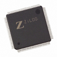
EZ80F93AZ020SC00TR Zilog, EZ80F93AZ020SC00TR Datasheet - Page 3

EZ80F93AZ020SC00TR
Manufacturer Part Number
EZ80F93AZ020SC00TR
Description
IC ACCLAIM MCU 64KB 100LQFP
Manufacturer
Zilog
Series
eZ80® Acclaim!®r
Specifications of EZ80F93AZ020SC00TR
Core Processor
Z8
Core Size
8-Bit
Speed
20MHz
Connectivity
I²C, IrDA, SPI, UART/USART
Peripherals
Brown-out Detect/Reset, POR, WDT
Number Of I /o
24
Program Memory Size
64KB (64K x 8)
Program Memory Type
FLASH
Ram Size
4K x 8
Voltage - Supply (vcc/vdd)
3 V ~ 3.6 V
Oscillator Type
Internal
Operating Temperature
0°C ~ 70°C
Package / Case
100-LQFP
Lead Free Status / RoHS Status
Contains lead / RoHS non-compliant
Eeprom Size
-
Data Converters
-
Other names
EZ80F93AZ020SC00T
Available stocks
Company
Part Number
Manufacturer
Quantity
Price
Table 1. Errata to eZ80F92 and eZ80F93 Devices (Continued)
UP004909-0910
No
6
Issue
GPIO edge-trigger
interrupt mapping error
Detailed Description
For edge triggered interrupts (Mode 6 and Mode 9), erroneous logic
dependencies for the interrupt clearing logic exist on all port pins within
each of the specific ports. To achieve proper interrupt clearing behavior
for a particular port pin its mirror pin must be programmed in a similar
manner. This affects how the designer utilizes GPIO alternate function
pins with GPIO interrupt modalities of those port pins.
The definition mirrored pin refers to any port in which for Port X, pin 0 is
mirrored to pin 7, pin 1 is mirrored to pin 6, pin 2 is mirrored to pin 5, and
pin 3 is mirrored to pin 4.
Note: X is defined as Port B, C, or D.
For example, if PB0 is programmed as an edge triggered interrupt, the
logic dependency to clear the interrupt by writing to PB0_DR and
protecting the actual PB0_DR register value from change comes from
the mirror pin PB7 logic. This is an errata problem which causes erratic
behavior problems.
In the above example, the problem is that PB0_DR itself can be altered
and might change the mode of operation for the port pin PB0. To
correctly set up the logic dependencies, the mirrored pin must be placed
in the same mode as its counterpart. As the functionally of these port
pins need to be mirrored in order to correct the logic dependency, the
alternate function assignments of these ports would not work correctly.
To use the SPI alternate function modality (for example, SPI alternate
function pins PB2, PB3, PB6, and PB7) you will not be able to use the
mirror port pins PB5, PB4, PB1, and PB0 for Mode 6 and Mode 9
interrupt and vice versa.
Any Port pin configured with Mode 6 or Mode 9 (an edge triggered
interrupt) exhibits this behavior and affects the alternate function
modality. The mirror mapping affects all Ports, specifically within the
respective port pin pairs 0 and 7, 1 and 6, 2 and 5, and 3 and 4.
Note: This design flaw in no way affects the IVECT address for the
GPIO interrupts.
Workaround
Below is an example setup:
PB0 Input, falling edge interrupt
PB1 Input, dual edge interrupt
PB2 Input, falling edge interrupt
(continued)
Product Update: Errata for eZ80F92 and eZ80F93 MCUs
Page 3 of 7


