M38039G6HSP#U0 Renesas Electronics America, M38039G6HSP#U0 Datasheet - Page 81
M38039G6HSP#U0
Manufacturer Part Number
M38039G6HSP#U0
Description
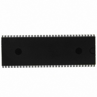
IC 740/3803 MCU QZROM 64DIP
Manufacturer
Renesas Electronics America
Series
740/38000r
Datasheet
1.M38039G4HHPU0.pdf
(105 pages)
Specifications of M38039G6HSP#U0
Core Processor
740
Core Size
8-Bit
Speed
16.8MHz
Connectivity
SIO, UART/USART
Peripherals
LED, PWM, WDT
Number Of I /o
56
Program Memory Size
24KB (24K x 8)
Program Memory Type
QzROM
Ram Size
2K x 8
Voltage - Supply (vcc/vdd)
1.8 V ~ 5.5 V
Data Converters
A/D 16x10b; D/A 2x8b
Oscillator Type
Internal
Operating Temperature
-20°C ~ 85°C
Package / Case
64-SDIP (0.750", 19.05mm)
Lead Free Status / RoHS Status
Lead free / RoHS Compliant
Eeprom Size
-


3803 Group (Spec.H QzROM version)
REJ03B0166-0113 Rev.1.13
Page 79 of 100
6. Serial Interface
In clock synchronous serial I/O, if the receive side is using an
external clock and it is to output the S
enable bit, the receive enable bit, and the S
to “1”.
Serial I/O1 continues to output the final bit from the T
after transmission is completed. S
high impedance after transfer is completed.
When in serial I/Os 1 and 3 (clock-synchronous mode) or in
serial I/O2, an external clock is used as synchronous clock, write
transmission data to the transmit buffer register or serial I/O2
register, during transfer clock is “H”.
7. A/D Converter
The comparator uses capacitive coupling amplifier whose charge
will be lost if the clock frequency is too low.
Therefore, make sure that f(X
is at least on 500 kHz during an A/D conversion.
Do not execute the STP instruction during an A/D conversion.
8. D/A Converter
The accuracy of the D/A converter becomes rapidly poor under
the V
V is recommended. When a D/A converter is not used, set all
values of DAi conversion registers (i=1, 2) to “00
9. Instruction Execution Time
The instruction execution time is obtained by multiplying the
period of the internal clock φ by the number of cycles needed to
execute an instruction.
The number of cycles required to execute an instruction is shown
in the list of machine instructions.
The period of the internal clock φ is double of the X
high-speed mode.
10.Reserved Area, Reserved Bit
Do not write any data to the reserved area in the SFR area and the
special page. (Do not change the contents after reset.)
11.CPU Mode Register
Be sure to fix bit 3 of the CPU mode register (address 003B
“1”.
CC
= 4.0 V or less condition; a supply voltage of V
IN
) in the middle/high-speed mode
OUT2
RDY
Aug 21, 2009
pin for serial I/O2 goes to
signal, set the transmit
RDY
output enable bit
16
”.
IN
period in
CC
X
D
16
≥ 4.0
1
) to
pin
COUNTERMEASURES AGAINST NOISE
(1) Shortest wiring length
1. Wiring for RESET pin
• Reason
The width of a pulse input into the RESET pin is determined by
the timing necessary conditions. If noise having a shorter pulse
width than the standard is input to the RESET pin, the reset is
released before the internal state of the microcomputer is
completely initialized. This may cause a program runaway.
Fig. 76 Wiring for the RESET pin
2. Wiring for clock input/output pins
• Reason
If noise enters clock I/O pins, clock waveforms may be
deformed.
This may cause a program failure or program runaway. Also, if a
potential difference is caused by the noise between the V
of a microcomputer and the V
clock will not be input in the microcomputer.
Fig. 77 Wiring for clock I/O pins
Make the length of wiring which is connected to the RESET
pin as short as possible. Especially, connect a capacitor across
the RESET pin and the V
wiring (within 20 mm).
• Make the length of wiring which is connected to clock I/O
• Make the length of wiring (within 20 mm) across the
• Separate the V
Reset
circuit
pins as short as possible.
grounding lead of a capacitor which is connected to an
oscillator and the V
possible.
patterns.
V
SS
N.G.
Noise
N.G.
Noise
SS
pattern only for oscillation from other V
X
X
V
IN
OUT
SS
RESET
V
SS
SS
pin of a microcomputer as short as
SS
SS
level of an oscillator, the correct
pin with the shortest possible
Reset
circuit
O.K.
V
SS
O.K.
X
X
V
RESET
V
IN
OUT
SS
SS
SS
level
SS
Related parts for M38039G6HSP#U0
Image
Part Number
Description
Manufacturer
Datasheet
Request
R

Part Number:
Description:
KIT STARTER FOR M16C/29
Manufacturer:
Renesas Electronics America
Datasheet:

Part Number:
Description:
KIT STARTER FOR R8C/2D
Manufacturer:
Renesas Electronics America
Datasheet:

Part Number:
Description:
R0K33062P STARTER KIT
Manufacturer:
Renesas Electronics America
Datasheet:

Part Number:
Description:
KIT STARTER FOR R8C/23 E8A
Manufacturer:
Renesas Electronics America
Datasheet:

Part Number:
Description:
KIT STARTER FOR R8C/25
Manufacturer:
Renesas Electronics America
Datasheet:

Part Number:
Description:
KIT STARTER H8S2456 SHARPE DSPLY
Manufacturer:
Renesas Electronics America
Datasheet:

Part Number:
Description:
KIT STARTER FOR R8C38C
Manufacturer:
Renesas Electronics America
Datasheet:

Part Number:
Description:
KIT STARTER FOR R8C35C
Manufacturer:
Renesas Electronics America
Datasheet:

Part Number:
Description:
KIT STARTER FOR R8CL3AC+LCD APPS
Manufacturer:
Renesas Electronics America
Datasheet:
Part Number:
Description:
KIT STARTER FOR RX610
Manufacturer:
Renesas Electronics America
Datasheet:

Part Number:
Description:
KIT STARTER FOR R32C/118
Manufacturer:
Renesas Electronics America
Datasheet:

Part Number:
Description:
KIT DEV RSK-R8C/26-29
Manufacturer:
Renesas Electronics America
Datasheet:

Part Number:
Description:
KIT STARTER FOR SH7124
Manufacturer:
Renesas Electronics America
Datasheet:

Part Number:
Description:
KIT STARTER FOR H8SX/1622
Manufacturer:
Renesas Electronics America
Datasheet:

Part Number:
Description:
KIT DEV FOR SH7203
Manufacturer:
Renesas Electronics America
Datasheet: