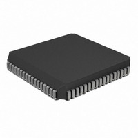
PIC17LC756AT-08/L Microchip Technology, PIC17LC756AT-08/L Datasheet - Page 59

PIC17LC756AT-08/L
Manufacturer Part Number
PIC17LC756AT-08/L
Description
IC MCU OTP 16KX16 A/D 68PLCC
Manufacturer
Microchip Technology
Series
PIC® 17Cr
Specifications of PIC17LC756AT-08/L
Core Processor
PIC
Core Size
8-Bit
Speed
8MHz
Connectivity
I²C, SPI, UART/USART
Peripherals
Brown-out Detect/Reset, POR, PWM, WDT
Number Of I /o
50
Program Memory Size
32KB (16K x 16)
Program Memory Type
OTP
Ram Size
902 x 8
Voltage - Supply (vcc/vdd)
3 V ~ 5.5 V
Data Converters
A/D 12x10b
Oscillator Type
External
Operating Temperature
0°C ~ 70°C
Package / Case
68-PLCC
Processor Series
PIC17LC
Core
PIC
Data Bus Width
8 bit
Data Ram Size
902 B
Interface Type
I2C, MSSP, RS- 232, SCI, SPI, USART
Maximum Clock Frequency
8 MHz
Number Of Programmable I/os
50
Number Of Timers
8
Operating Supply Voltage
3 V to 5.5 V
Maximum Operating Temperature
+ 70 C
Mounting Style
SMD/SMT
Minimum Operating Temperature
0 C
On-chip Adc
12 bit
Data Rom Size
902 B
Height
4.06 mm
Length
24.33 mm
Supply Voltage (max)
5.5 V
Supply Voltage (min)
3 V
Width
24.33 mm
Lead Free Status / RoHS Status
Lead free / RoHS Compliant
Eeprom Size
-
Lead Free Status / Rohs Status
Details
Available stocks
Company
Part Number
Manufacturer
Quantity
Price
Company:
Part Number:
PIC17LC756AT-08/L
Manufacturer:
Microchip Technology
Quantity:
10 000
- Current page: 59 of 304
- Download datasheet (6Mb)
8.0
The PIC17C7XX has four instructions that allow the
processor to move data from the data memory space to
the program memory space, and vice versa. Since the
program memory space is 16-bits wide and the data
memory space is 8-bits wide, two operations are
required to move 16-bit values to/from the data
memory.
The TLWT t,f and TABLWT t,i,f instructions are
used to write data from the data memory space to the
program memory space. The TLRD t,f and TABLRD
t,i,f instructions are used to write data from the pro-
gram memory space to the data memory space.
The program memory can be internal or external. For
the program memory access to be external, the device
needs to be operating in Microprocessor or Extended
Microcontroller mode.
Figure 8-1 through Figure 8-4 show the operation of
these four instructions. The steps show the sequence
of operation.
FIGURE 8-1:
Step 1: 8-bit value from register ’f’, loaded into the high or low
2000 Microchip Technology Inc.
Memory
Data
f
TABLE READS AND TABLE
WRITES
byte in TABLAT (16-bit).
TABLE POINTER
TABLE LATCH (16-bit)
TLWT 1,f
1
TBLPTRH
TABLATH
TLWT INSTRUCTION
OPERATION
TBLPTRL
TABLATL
TLWT 0,f
Program Memory
FIGURE 8-2:
Step 1: 8-bit value from register ’f’, loaded into the high or low
Memory
Data
2: 16-bit TABLAT value written to address Program Memory
3: If “i” = 1, then TBLPTR = TBLPTR + 1,
f
TABLWT 1,i,f
byte in TABLAT (16-bit).
(TBLPTR).
If “i” = 0, then TBLPTR is unchanged.
TABLE POINTER
TABLE LATCH (16-bit)
1
3
TBLPTRH
TABLATH
TABLWT INSTRUCTION
OPERATION
Prog-Mem
(TBLPTR)
PIC17C7XX
2
TBLPTRL
TABLATL
TABLWT 0,i,f
Program Memory
DS30289B-page 59
3
Related parts for PIC17LC756AT-08/L
Image
Part Number
Description
Manufacturer
Datasheet
Request
R

Part Number:
Description:
MICRO CTRL 16K LOW PWR 68PLCC
Manufacturer:
Microchip Technology
Datasheet:

Part Number:
Description:
MICRO CTRL 16K LOW PWR 64SDIP
Manufacturer:
Microchip Technology
Datasheet:

Part Number:
Description:
MICRO CTRL 16K LOW PWR 64SDIP
Manufacturer:
Microchip Technology
Datasheet:

Part Number:
Description:
MICRO CTRL 16K LOW PWR 68PLCC
Manufacturer:
Microchip Technology
Datasheet:

Part Number:
Description:
Manufacturer:
Microchip Technology Inc.
Datasheet:

Part Number:
Description:
Manufacturer:
Microchip Technology Inc.
Datasheet:

Part Number:
Description:
Manufacturer:
Microchip Technology Inc.
Datasheet:

Part Number:
Description:
Manufacturer:
Microchip Technology Inc.
Datasheet:

Part Number:
Description:
Manufacturer:
Microchip Technology Inc.
Datasheet:

Part Number:
Description:
Manufacturer:
Microchip Technology Inc.
Datasheet:

Part Number:
Description:
Manufacturer:
Microchip Technology Inc.
Datasheet:


