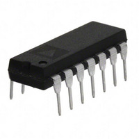
OP482GPZ Analog Devices Inc, OP482GPZ Datasheet - Page 12

OP482GPZ
Manufacturer Part Number
OP482GPZ
Description
IC OPAMP JFET 4MHZ QUAD LP 14DIP
Manufacturer
Analog Devices Inc
Specifications of OP482GPZ
Slew Rate
9 V/µs
Amplifier Type
General Purpose
Number Of Circuits
4
Gain Bandwidth Product
4MHz
Current - Input Bias
3pA
Voltage - Input Offset
200µV
Current - Supply
210µA
Current - Output / Channel
12mA
Voltage - Supply, Single/dual (±)
9 V ~ 36 V, ±4.5 V ~ 18 V
Operating Temperature
-40°C ~ 85°C
Mounting Type
Through Hole
Package / Case
14-DIP (0.300", 7.62mm)
Op Amp Type
Low Power
No. Of Amplifiers
4
Bandwidth
4MHz
Supply Voltage Range
± 4.5V To ± 18V
Amplifier Case Style
DIP
No. Of Pins
14
Operating Temperature Range
-40°C To +85°C
Common Mode Rejection Ratio
90
Current, Input Bias
3 pA
Current, Input Offset
1 pA
Current, Output
10 mA
Current, Supply
210 μA
Impedance, Thermal
39 °C/W
Number Of Amplifiers
Quad
Package Type
PDIP-14
Temperature, Operating, Range
-40 to +85 °C
Voltage, Gain
20 V/mV
Voltage, Input
-11 to +15 V
Voltage, Noise
36 nV/sqrt Hz
Voltage, Offset
0.2 mV
Voltage, Output, High
13.9 V
Voltage, Output, Low
-13.9 V
Voltage, Supply
±15 V
Lead Free Status / RoHS Status
Lead free / RoHS Compliant
Output Type
-
-3db Bandwidth
-
Lead Free Status / Rohs Status
RoHS Compliant part
Electrostatic Device
OP282/OP482
APPLICATIONS INFORMATION
The OP282 and OP482 are dual and quad JFET op amps that
are optimized for high speed at low power. This combination
makes these amplifiers excellent choices for battery-powered or
low power applications that require above average performance.
Applications benefiting from this performance combination
include telecommunications, geophysical exploration, portable
medical equipment, and navigational instrumentation.
HIGH-SIDE SIGNAL CONDITIONING
There are many applications that require the sensing of signals
near the positive rail. OP282s and OP482s were tested and are
guaranteed over a common-mode range (−11 V ≤ V
that includes the positive supply.
One application where this is commonly used is in the sensing
of power supply currents. This enables it to be used in current
sensing applications, such as the partial circuit shown in Figure 44.
In this circuit, the voltage drop across a low value resistor, such
as the 0.1 Ω shown here, is amplified and compared to 7.5 V.
The output can then be used for current limiting.
Table 4.
Type
Butterworth
Chebyshev
Elliptical
Bessel (Thompson)
15V
500k Ω
100k Ω
0.1 Ω
100k Ω
Figure 44. High-Side Signal Conditioning
Selectivity
Moderate
Good
Best
Poor
500k Ω
OP282
1/2
Overshoot
Good
Moderate
Poor
Best
CM
≤ +15 V)
R
L
Rev. F | Page 12 of 16
Phase
Nonlinear
Linear
PHASE INVERSION
Most JFET-input amplifiers invert the phase of the input signal
if either input exceeds the input common-mode range. For the
OP282/OP482, negative signals in excess of approximately 14 V
cause phase inversion. The cause of this effect is saturation of
the input stage leading to the forward-biasing of a drain-gate
diode. A simple fix for this in noninverting applications is to
place a resistor in series with the noninverting input. This limits
the amount of current through the forward-biased diode and
prevents the shutting down of the output stage. For the
OP282/OP482, a value of 200 kΩ has been found to work;
however, this adds a significant amount of noise.
ACTIVE FILTERS
The wide bandwidth and high slew rates of the OP282/OP482
make either an excellent choice for many filter applications.
There are many active filter configurations, but the four most
popular configurations are Butterworth, Elliptical, Bessel, and
Chebyshev. Each type has a response that is optimized for a
given characteristic as shown in Table 4.
Amplitude (Pass Band)
Maximum Flat
Equal Ripple
Equal Ripple
– 10
– 15
15
10
– 5
5
0
–15
–10
Figure 45. OP282 Phase Reversal
–5
V
0
IN
Amplitude (Stop Band)
Equal Ripple
5
10
15


