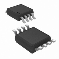
LMV822MM/NOPB National Semiconductor, LMV822MM/NOPB Datasheet - Page 14

LMV822MM/NOPB
Manufacturer Part Number
LMV822MM/NOPB
Description
IC OP AMP R-R LOW VOLT LP 8-MSOP
Manufacturer
National Semiconductor
Datasheet
1.LMV821M5NOPB.pdf
(24 pages)
Specifications of LMV822MM/NOPB
Amplifier Type
General Purpose
Number Of Circuits
2
Output Type
Rail-to-Rail
Slew Rate
2 V/µs
Gain Bandwidth Product
5.6MHz
Current - Input Bias
100nA
Voltage - Input Offset
3500µV
Current - Supply
500µA
Current - Output / Channel
45mA
Voltage - Supply, Single/dual (±)
2.5 V ~ 5.5 V, ±1.25 V ~ 2.75 V
Operating Temperature
-40°C ~ 85°C
Mounting Type
Surface Mount
Package / Case
8-MSOP, Micro8™, 8-uMAX, 8-uSOP,
Lead Free Status / RoHS Status
Lead free / RoHS Compliant
-3db Bandwidth
-
Other names
LMV822MM
LMV822MMTR
LMV822MMTR
Available stocks
Company
Part Number
Manufacturer
Quantity
Price
Part Number:
LMV822MM/NOPB
Manufacturer:
TI/德州仪器
Quantity:
20 000
Company:
Part Number:
LMV822MM/NOPB
Manufacturer:
NSC
Quantity:
10 669
www.national.com
Application Note
Table 1 provides sensitivity measurements for a 10 MΩ load
condition. The left column shows the passive components
for the 3 kHz low-pass DAAF. The third column shows the
components for the 300 Hz high-pass DAAF. Their respec-
tive sensitivity measurements are shown to the right of each
component column. Their values consists of the percent
change in cutoff frequency (Fc) divided by the percent
change in component value. The lower the sensitivity value,
the better the performance.
Each resistor value was changed by about 10 percent, and
this measured change was divided into the measured
change in Fc. A positive or negative sign in front of the
measured value, represents the direction Fc changes rela-
tive to components’ direction of change. For example, a
sensitivity value of negative 1.2, means that for a 1 percent
increase in component value, Fc decreases by 1.2 percent.
Filter with a Butterworth Response and a Pass Band
Filter with a Butterworth Response and a Pass Band
FIGURE 11. Dual Amplifier, 300 Hz High-Pass Active
FIGURE 10. Dual Amplifier, 3 kHz Low-Pass Active
Gain of Times Two
Gain of Times Two
(Continued)
10012836
10012837
14
Note that this information provides insight on how to fine
tune the cutoff frequency, if necessary. It should be also
noted that R
the pass band gain. Increasing R
the gain by 0.4 dB, while increasing R
decreased the gain by 0.4 dB.
Active filters are also sensitive to an op amp’s parameters
-Gain and Bandwidth, in particular. The LMV822/24 provide
a large gain and wide bandwidth. And DAAFs make excel-
lent use of these feature specifications.
Single Amplifier versions require a large open-loop to
closed-loop gain ratio - approximately 50 to 1, at the Fc of
the filter response. Figure 12 shows an impressive photo-
graph of a network analyzer measurement (hp3577A). The
measurement was taken from a 300 kHz version of Figure
10. At 300 kHz, the open-loop to closed-loop gain ratio
is about 5 to 1. This is 10 times lower than the 50 to 1 “rule
of thumb” for Single Amplifier Active Filters.
In addition to performance, DAAFs are relatively easy to
design and implement. The design equations for the low-
pass and high-pass DAAFs are shown below. The first two
equation calculate the Fc and the circuit Quality Factor (Q)
for the LPF (Figure 10). The second two equations calculate
the Fc and Q for the HPF (Figure 11).
FIGURE 12. 300 kHz, Low-Pass Filter, Butterworth
Component
Response as Measured by the HP3577A Network
(LPF)
R
C
R
R
C
R
R
a
1
2
3
3
4
5
4
and R
Sensitivity
5
(LPF)
+0.7
+0.6
of each circuit also caused variations in
-1.2
-0.1
-1.1
-1.5
-0.6
TABLE 1.
Analyzer
Component
4
(HPF)
by ten percent, increased
C
R
R
C
R
R
R
a
b
1
2
3
4
5
5
by ten percent,
Sensitivity
10012892
(HPF)
+0.1
+0.1
+0.1
-0.7
-1.0
-0.1
-0.1
@
Fc


