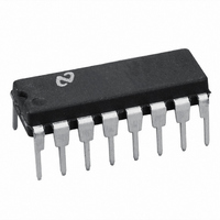
LM13700N/NOPB National Semiconductor, LM13700N/NOPB Datasheet - Page 8

LM13700N/NOPB
Manufacturer Part Number
LM13700N/NOPB
Description
IC AMP DUAL OP TRANSCOND 16-DIP
Manufacturer
National Semiconductor
Datasheet
1.LM13700NNOPB.pdf
(26 pages)
Specifications of LM13700N/NOPB
Amplifier Type
Transconductance
Number Of Circuits
2
Output Type
Push-Pull
Slew Rate
50 V/µs
Gain Bandwidth Product
2MHz
Current - Input Bias
1µA
Voltage - Input Offset
300µV
Current - Supply
2.6mA
Current - Output / Channel
650µA
Voltage - Supply, Single/dual (±)
10 V ~ 36 V, ±5 V ~ 18 V
Operating Temperature
0°C ~ 70°C
Mounting Type
Through Hole
Package / Case
16-DIP (0.300", 7.62mm)
Lead Free Status / RoHS Status
Lead free / RoHS Compliant
-3db Bandwidth
-
Other names
*LM13700N
*LM13700N/NOPB
LM13700N
*LM13700N/NOPB
LM13700N
www.national.com
Applications
Voltage Controlled Amplifiers
For optimum signal-to-noise performance, I
large as possible as shown by the Output Voltage vs. Ampli-
fier Bias Current graph. Larger amplitudes of input signal
also improve the S/N ratio. The linearizing diodes help here
by allowing larger input signals for the same output distortion
as shown by the Distortion vs. Differential Input Voltage
graph. S/N may be optimized by adjusting the magnitude of
the input signal via R
below some desired level. The output voltage swing can
then be set at any level by selecting R
IN
(Figure 2) until the output distortion is
L
.
FIGURE 2. Voltage Controlled Amplifier
ABC
should be as
FIGURE 1. Linearizing Diodes
(Continued)
8
Although the noise contribution of the linearizing diodes is
negligible relative to the contribution of the amplifier’s inter-
nal transistors, I
mizes the dynamic junction resistance of the diodes (r
maximizes their linearizing action when balanced against
R
specific application demands otherwise.
IN
. A value of 1 mA is recommended for I
D
should be as large as possible. This mini-
00798109
00798108
D
unless the
e
) and


