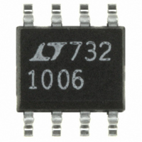
LT1006S8 Linear Technology, LT1006S8 Datasheet - Page 9

LT1006S8
Manufacturer Part Number
LT1006S8
Description
IC PREC OP-AMP 5V SINGLE 8-SOIC
Manufacturer
Linear Technology
Datasheet
1.LT1006CN8PBF.pdf
(16 pages)
Specifications of LT1006S8
Amplifier Type
General Purpose
Number Of Circuits
1
Slew Rate
1.2 V/µs
Current - Input Bias
10nA
Voltage - Input Offset
80µV
Current - Supply
360µA
Voltage - Supply, Single/dual (±)
5 V ~ 30 V, ±2.5 V ~ 15 V
Operating Temperature
0°C ~ 70°C
Mounting Type
Surface Mount
Package / Case
8-SOIC (3.9mm Width)
Lead Free Status / RoHS Status
Contains lead / RoHS non-compliant
Output Type
-
Current - Output / Channel
-
-3db Bandwidth
-
Gain Bandwidth Product
-
Available stocks
Company
Part Number
Manufacturer
Quantity
Price
Company:
Part Number:
LT1006S8
Manufacturer:
LT
Quantity:
10 000
Part Number:
LT1006S8
Manufacturer:
LINEAR/凌特
Quantity:
20 000
Company:
Part Number:
LT1006S8#PBF
Manufacturer:
LT
Quantity:
8 872
Part Number:
LT1006S8#PBF
Manufacturer:
LINEAR/凌特
Quantity:
20 000
Company:
Part Number:
LT1006S8#TR
Manufacturer:
LT
Quantity:
12
Company:
Part Number:
LT1006S8#TRPBF
Manufacturer:
LT
Quantity:
4 300
Part Number:
LT1006S8#TRPBF
Manufacturer:
LINEAR/凌特
Quantity:
20 000
Company:
Part Number:
LT1006S8TR
Manufacturer:
PHIL
Quantity:
4 580
APPLICATIO S I FOR ATIO
The LT1006 is fully specified for single supply operation,
(i.e., when the negative supply is 0V). Input common
mode range includes ground; the output swings within a
few millivolts of ground. Single supply operation, how-
ever, can create special difficulties, both at the input and
at the output. The LT1006 has specific circuitry which
addresses these problems.
At the input, the driving signal can fall below 0V—
inadvertently or on a transient basis. If the input is more
than a few hundred millivolts below ground, two distinct
problems can occur on previous single supply designs,
such as the LM124, LM158, OP-20, OP-21, OP-220,
OP-221, OP-420:
a) When the input is more than a diode drop below ground,
unlimited current will flow from the substrate (V
nal) to the input. This can destroy the unit. On the LT1006,
the 400Ω resistors, in series with the input (see Schematic
Diagram), protect the devices even when the input is 5V
below ground.
b) When the input is more than 400mV below ground
(at 25°C), the input stage saturates (transistors Q3 and
4V
2V
0V
6V
P-P
R
1mV
INPUT, –1.5V TO 4.5V
U
Gain 100 Amplifier
Voltage Follower with Input Exceeding the Negative Common Mode Range (V
–
+
LT1006
U
5V
1006 TA11a
W
99R
600Ω
LT1006 • TA02
100mV
4V
2V
0V
U
–
termi-
LM324, LM358, OP-20, OP-21
EXHIBIT OUTPUT PHASE
REVERSAL
Q4) and phase reversal occurs at the output. This can
cause lock-up in servo systems. Due to a unique phase
reversal protection circuitry (Q21, Q22, Q27, Q28), the
LT1006’s output does not reverse, as illustrated below,
even when the inputs are at –1.5V.
At the output, the aforementioned single supply designs
either cannot swing to within 600mV of ground (OP-20)
or cannot sink more than a few microamperes while
swinging to ground (LM124, LM158). The LT1006’s
all-NPN output stage maintains its low output resistance
and high gain characteristics until the output is saturated.
In dual supply operations, the output stage is crossover
distortion free.
Since the output cannot go exactly to ground, but can only
approach ground to within a few millivolts, care should be
exercised to ensure that the output is not saturated. For
example, a 1mV input signal will cause the amplifier to set
up in its linear region in the gain 100 configuration shown
below, but is not enough to make the amplifier function
properly in the voltage follower mode.
1006 TA11b
1mV
Voltage Follower
–
+
4V
2V
0V
LT1006
S
5V
= 5V, 0V)
600Ω
NO PHASE REVERSAL
LT1006 • TA03
LT1006
OUTPUT
SATURATED
≈ 5mV
LT1006
1006 TA11c
1006fa
9


