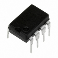
LMC662CN/NOPB National Semiconductor, LMC662CN/NOPB Datasheet - Page 10

LMC662CN/NOPB
Manufacturer Part Number
LMC662CN/NOPB
Description
IC OP AMP DUAL CMOS 8-DIP
Manufacturer
National Semiconductor
Type
General Purpose Amplifierr
Specifications of LMC662CN/NOPB
Amplifier Type
General Purpose
Number Of Circuits
2
Output Type
Rail-to-Rail
Slew Rate
1.1 V/µs
Gain Bandwidth Product
1.4MHz
Current - Input Bias
0.002pA
Voltage - Input Offset
1000µV
Current - Supply
750µA
Current - Output / Channel
40mA
Voltage - Supply, Single/dual (±)
4.75 V ~ 15.5 V, ±2.38 V ~ 7.75 V
Operating Temperature
0°C ~ 70°C
Mounting Type
Through Hole
Package / Case
8-DIP (0.300", 7.62mm)
Bandwidth
1.4 MHz
Channel Separation
130
Common Mode Rejection Ratio
83
Current, Input Bias
0.002 pA
Current, Input Offset
0.001 pA
Current, Output
40 mA
Current, Supply
0.75 mA
Harmonic Distortion
0.01 %
Impedance, Thermal
101 °C/W
Number Of Amplifiers
Dual
Package Type
MDIP-8
Resistance, Input
1 Teraohms
Temperature, Operating, Range
0 to +70 °C
Voltage, Gain
2000 V/mV
Voltage, Input
4.75 to 15.5 V
Voltage, Noise
22 nV/sqrt Hz
Voltage, Offset
1 mV
Voltage, Output, High
14.63 V
Voltage, Output, Low
0.26 V
Voltage, Supply
5 V
Rail/rail I/o Type
Rail to Rail Output
Number Of Elements
2
Unity Gain Bandwidth Product
1.4MHz
Input Offset Voltage
6mV
Input Bias Current
2fA
Single Supply Voltage (typ)
5/9/12/15V
Dual Supply Voltage (typ)
Not RequiredV
Voltage Gain In Db
126.02dB
Power Supply Rejection Ratio
63dB
Power Supply Requirement
Single
Shut Down Feature
No
Single Supply Voltage (min)
4.75V
Single Supply Voltage (max)
15.5V
Dual Supply Voltage (min)
Not RequiredV
Dual Supply Voltage (max)
Not RequiredV
Technology
CMOS
Operating Temp Range
0C to 70C
Operating Temperature Classification
Commercial
Mounting
Through Hole
Pin Count
8
Number Of Channels
2
Voltage Gain Db
126.02 dB
Common Mode Rejection Ratio (min)
63 dB
Input Voltage Range (max)
15.5 V
Input Voltage Range (min)
4.75 V
Operating Supply Voltage
5 V, 9 V, 12 V, 15 V
Supply Current
1.6 mA at 5 V
Maximum Operating Temperature
+ 70 C
Mounting Style
Through Hole
Minimum Operating Temperature
0 C
Lead Free Status / RoHS Status
Lead free / RoHS Compliant
-3db Bandwidth
-
Lead Free Status / Rohs Status
RoHS Compliant part
Electrostatic Device
Other names
*LMC662CN
*LMC662CN/NOPB
LMC662CN
*LMC662CN/NOPB
LMC662CN
www.national.com
Application Hints
BIAS CURRENT TESTING
The test method of Figure 11 is appropriate for bench-testing
bias current with reasonable accuracy. To understand its
operation, first close switch S2 momentarily. When S2 is
opened, then
FIGURE 11. Simple Input Bias Current Test Circuit
(Continued)
00976322
10
A suitable capacitor for C2 would be a 5 pF or 10 pF silver
mica, NPO ceramic, or air-dielectric. When determining the
magnitude of I
must be taken into account. Switch S2 should be left shorted
most of the time, or else the dielectric absorption of the
capacitor C2 could cause errors.
Similarly, if S1 is shorted momentarily (while leaving S2
shorted)
where C
x
is the stray capacitance at the + input.
b
−, the leakage of the capacitor and socket


