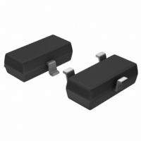
TCM810RENB713 Microchip Technology, TCM810RENB713 Datasheet - Page 5

TCM810RENB713
Manufacturer Part Number
TCM810RENB713
Description
IC RESET MONITOR 2.63V SOT23B
Manufacturer
Microchip Technology
Type
Simple Reset/Power-On Resetr
Specifications of TCM810RENB713
Number Of Voltages Monitored
1
Output
Push-Pull, Totem Pole
Reset
Active High
Reset Timeout
140 ms Minimum
Voltage - Threshold
2.63V
Operating Temperature
-40°C ~ 85°C
Mounting Type
Surface Mount
Package / Case
SOT-23-3, TO-236-3, Micro3™, SSD3, SST3
Threshold Voltage
2.63V
No. Of Supervisors / Monitors
1
Supply Voltage Range
1.2V To 5.5V
Reset Type
Active-High
Supply Current
9µA
Delay Time
320ms
Digital Ic Case Style
SOT-23
Monitored Voltage
2.5 V, 3 V, 3.3 V, 5 V
Output Type
Active High, Push-Pull
Manual Reset
Not Resettable
Watchdog
No Watchdog
Battery Backup Switching
No Backup
Supply Voltage (max)
5.5 V
Supply Voltage (min)
1 V
Supply Current (typ)
9 uA
Maximum Power Dissipation
320 mW
Maximum Operating Temperature
+ 85 C
Mounting Style
SMD/SMT
Minimum Operating Temperature
- 40 C
Power Fail Detection
No
Undervoltage Threshold
2.59 V
Overvoltage Threshold
2.66 V
Power-up Reset Delay (typ)
560 ms
Lead Free Status / RoHS Status
Lead free / RoHS Compliant
Lead Free Status / RoHS Status
Lead free / RoHS Compliant, Lead free / RoHS Compliant
Other names
158-2028-2
158-2028-2
TCM810RENB713TR
158-2028-2
TCM810RENB713TR
Available stocks
Company
Part Number
Manufacturer
Quantity
Price
Company:
Part Number:
TCM810RENB713
Manufacturer:
Microchip Technology
Quantity:
15 450
Part Number:
TCM810RENB713
Manufacturer:
MICROCHIP/微芯
Quantity:
20 000
4.0
4.1
The TCM809/TCM810 provides accurate V
ing and reset timing during power-up, power-down and
brown-out/sag conditions. These devices also reject
negative-going transients (glitches) on the power
supply line. Figure 4-1 shows the maximum transient
duration vs. maximum negative excursion (overdrive)
for glitch rejection. Any combination of duration and
overdrive that lies under the curve will not generate a
reset signal.
FIGURE 4-1:
Duration vs. Overdrive for Glitch Rejection at
+25°C.
© 2005 Microchip Technology Inc.
130
120
110
100
90
80
70
60
50
40
30
1
APPLICATIONS INFORMATION
V
400
320
240
160
80
DD
0
V
1
TCM8XXZ/R/S/T
Reset Comparator Overdrive (mV)
(SOT-23)
Transient Rejection
DD
T
A
Reset Comparator Overdrive
= +25°C
[V
10
Maximum Transient
Duration
TH
[V
5
TCM8XXL/M/J (SOT-23)
TH
– V
– V
DD
TCM8XXZ/R/S/T (SC-70)
] (mv)
DD
TCM8XXL/M/J (SC-70)
Overdrive
] (mv)
V
100
TH
100
DD
1000
monitor-
1000
Combinations above the curve are detected as a
brown-out
immunity can be improved by adding a capacitor in
close proximity to the V
4.2
The TCM809 RESET output is valid to V
Below this voltage the output becomes an "open cir-
cuit" and does not sink current. This means CMOS
logic inputs to the microcontroller will be floating at an
undetermined voltage. Most digital systems are
completely shut down well above this voltage.
However, in situations where RESET must be main-
tained valid to V
connected from RESET to ground to discharge stray
capacitances and hold the output low (Figure 4-2). This
resistor value, though not critical, should be chosen
such that it does not appreciably load RESET under
normal operation (100 k
applications). Similarly, a pull-up resistor to V
required for the TCM810 to ensure a valid high RESET
for V
FIGURE 4-2:
RESET output of the TCM809 ensures that the
RESET output is valid to V
DD
below 1.0V.
RESET Signal Integrity During
Power-Down
TCM809/TCM810
or
TCM809
DD
power-down
GND
V
V
= 0V, a pull-down resistor must be
DD
DD
RESET
The addition of R
DD
pin of the TCM809/TCM810.
will be suitable for most
DD
condition.
= 0V.
R
100 k
1
DS21661D-page 5
1
DD
at the
Transient
= 1.0V.
DD
is


