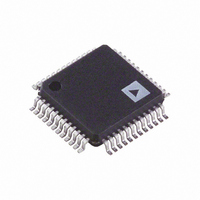
ADM1064ASUZ Analog Devices Inc, ADM1064ASUZ Datasheet - Page 20

ADM1064ASUZ
Manufacturer Part Number
ADM1064ASUZ
Description
IC SEQUENCER/SUPERVISOR 48-TQFP
Manufacturer
Analog Devices Inc
Type
Sequencerr
Datasheet
1.EVAL-ADM1064TQEB.pdf
(32 pages)
Specifications of ADM1064ASUZ
Number Of Voltages Monitored
10
Output
Programmable
Voltage - Threshold
Adjustable/Selectable
Operating Temperature
-40°C ~ 85°C
Mounting Type
Surface Mount
Package / Case
48-TQFP, 48-VQFP
No. Of Supervisors / Monitors
10
Supply Voltage Range
3V To 14.4V
Supply Current
4.2mA
Digital Ic Case Style
TQFP
No. Of Pins
48
Operating Temperature Range
-40°C To +85°C
Svhc
No SVHC
Lead Free Status / RoHS Status
Lead free / RoHS Compliant
For Use With
EVAL-ADM1064LFEBZ - BOARD EVALUATION FOR ADM1064LFEVAL-ADM1064TQEB - BOARD EVALUATION FOR ADM1064TQ
Reset
-
Reset Timeout
-
Lead Free Status / RoHS Status
Lead free / RoHS Compliant, Lead free / RoHS Compliant
Available stocks
Company
Part Number
Manufacturer
Quantity
Price
Company:
Part Number:
ADM1064ASUZ
Manufacturer:
ADI
Quantity:
250
Company:
Part Number:
ADM1064ASUZ
Manufacturer:
Analog Devices Inc
Quantity:
10 000
Part Number:
ADM1064ASUZ
Manufacturer:
ADI/亚德诺
Quantity:
20 000
ADM1064
VOLTAGE READBACK
The ADM1064 has an on-board 12-bit accurate ADC for
voltage readback over the SMBus. The ADC has a 12-channel
analog mux on the front end. The 12 channels consist of the
10 SFD inputs (VH, VPx, and VXx) and two auxiliary (single-
ended) ADC inputs (AUX1 and AUX2). Any or all of these
inputs can be selected to be read, in turn, by the ADC. The
circuit controlling this operation is called the round-robin
circuit. This circuit can be selected to run through its loop of
conversions once or continuously. Averaging is also provided
for each channel. In this case, the round-robin circuit runs through
its loop of conversions 16 times before returning a result for each
channel. At the end of this cycle, the results are written to the
output registers.
The ADC samples single-sided inputs with respect to the
AGND pin. A 0 V input gives out Code 0, and an input equal to
the voltage on REFIN gives out full code (4095 decimal).
The inputs to the ADC come directly from the VXx pins and
from the back of the input attenuators on the VPx and VH pins,
as shown in Figure 27 and Figure 28.
The voltage at the input pin can be derived from the following
equation:
where V
is, the REFIN pin is connected to the REFOUT pin).
The ADC input voltage ranges for the SFD input ranges are
listed in Table 9.
V =
VPx/VH
REFIN
ADC
4095
= 2.048 V when the internal reference is used (that
VXx
Code
Figure 28. ADC Reading on VPx/VH Pins
Figure 27. ADC Reading on VXx Pins
ATTENUATION NETWORK
(DEPENDS ON RANGE SELECTED)
NO ATTENUATION
× Attenuation Factor × V
2.048V VREF
12-BIT
ADC
2.048V VREF
12-BIT
ADC
DIGITIZED
VOLTAGE
READING
DIGITIZED
VOLTAGE
READING
REFIN
Rev. C | Page 20 of 32
Table 9. ADC Input Voltage Ranges
SFD Input
Range (V)
0.573 to 1.375
1.25 to 3.00
2.5 to 6.0
6.0 to 14.4
1
VH pins.
The typical way to supply the reference to the ADC on the
REFIN pin is to connect the REFOUT pin to the REFIN pin.
REFOUT provides a 2.048 V reference. As such, the supervising
range covers less than half the normal ADC range. It is possible,
however, to provide the ADC with a more accurate external
reference for improved readback accuracy.
Supplies can also be connected to the input pins purely for ADC
readback, even though these pins may go above the expected
supervisory range limits (but not above the absolute maximum
ratings on these pins). For example, a 1.5 V supply connected to
the VX1 pin can be correctly read out as an ADC code of approxi-
mately 3/4 full scale, but it always sits above any supervisory limits
that can be set on that pin. The maximum setting for the REFIN
pin is 2.048 V.
SUPPLY SUPERVISION WITH THE ADC
In addition to the readback capability, another level of supervi-
sion is provided by the on-chip, 12-bit ADC. The ADM1064 has
limit registers with which the user can program a maximum or
minimum allowable threshold. Exceeding the threshold generates
a warning that can either be read back from the status registers
or input into the SE to determine what sequencing action the
ADM1064 should take. Only one register is provided for each input
channel. Therefore, either an undervoltage threshold or overvoltage
threshold (but not both) can be set for a given channel. The round-
robin circuit can be enabled via an SMBus write, or it can be
programmed to turn on in any state in the SE program. For
example, it can be set to start after a power-up sequence is
complete, and all supplies are known to be within expected
tolerance limits.
Note that a latency is built into this supervision, dictated by the
conversion time of the ADC. With all 12 channels selected, the
total time for the round-robin operation (averaging off) is
approximately 6 ms (500 μs per channel selected). Supervision
using the ADC, therefore, does not provide the same real-time
response as the SFDs.
The upper limit is the absolute maximum allowed voltage on the VPx and
Attenuation Factor
1
2.181
4.363
10.472
ADC Input Voltage
Range (V)
0 to 2.048
0 to 4.46
0 to 6.0
0 to 14.4
1
1


