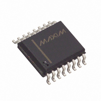
MAX807MEWE+ Maxim Integrated Products, MAX807MEWE+ Datasheet - Page 12

MAX807MEWE+
Manufacturer Part Number
MAX807MEWE+
Description
IC SUPERVISOR MPU 16-SOIC
Manufacturer
Maxim Integrated Products
Type
Battery Backup Circuitr
Datasheet
1.MAX807NEWE.pdf
(16 pages)
Specifications of MAX807MEWE+
Number Of Voltages Monitored
1
Reset
Active High/Active Low
Reset Timeout
140 ms Minimum
Voltage - Threshold
4.575V
Operating Temperature
-40°C ~ 85°C
Mounting Type
Surface Mount
Package / Case
16-SOIC (0.300", 7.5mm Width)
Monitored Voltage
4.425 V
Output Type
Active High, Active Low
Manual Reset
Resettable
Watchdog
Watchdog
Battery Backup Switching
Backup
Supply Voltage (max)
5.5 V
Supply Voltage (min)
0 V
Supply Current (typ)
70 uA
Maximum Power Dissipation
762 mW
Maximum Operating Temperature
+ 85 C
Mounting Style
SMD/SMT
Minimum Operating Temperature
- 40 C
Power Fail Detection
Yes
Undervoltage Threshold
4.35 V
Overvoltage Threshold
4.5 V
Power-up Reset Delay (typ)
280 ms
Lead Free Status / RoHS Status
Lead free / RoHS Compliant
Output
-
Lead Free Status / Rohs Status
Lead free / RoHS Compliant
Full-Featured µP Supervisory Circuit with
±1.5% Reset Accuracy
Figure 10. Using the Power-Fail Comparator to Monitor an Additional Power Supply: a) V
Figure 11. a) If the preregulated supply is inaccessible, LOW
LINE generates the NMI for the µP. b) Use PFO to generate the
µP NMI if the preregulated supply is accessible.
12
REGULATED
a)
b)
SUPPLY
a)
REGULATOR
______________________________________________________________________________________
FROM
VOLTAGE
0.1µF
PFO
V
V
TRIP
CC
V
L
= R2
= R2
R1
R2
V
(V
V
(V
0.1µF
IN
CC
PFT
PFT
MAX807
)
+ V
GND
(
LOW LINE
PFI
PFH
1
R1
V
CC
RESET
+
)
MAX807
BATT
OUT
WDI
(
R2
1
GND
R1
1
)
+
–
RESET
PFI
BATT
1
R2
V
OUT
PFO
WDI
R1
CC
V
L
)
–
2.8V
0.1µF
MAX807
V
CC
R1
V
V
GND
TRIP
CC
2.8V
0.1µF
POWER TO
CMOS RAM
RESET
NMI
I/O LINE
WHERE
NOTE: V
µP POWER
PFO
µP
0V
RESET
NMI
I/O LINE
TRIP,
POWER TO
CMOS RAM
V
V
PFT
PFH
µP POWER
V
= 2.265V
µP
= 20mV
L
ARE NEGATIVE.
V
IN
PFI is the noninverting input to an uncommitted com-
parator. If PFI is less than V
The power-fail comparator is intended to monitor the
preregulated input of the power supply, providing an
early power-fail warning so software can conduct an
orderly shutdown. It can also be used to monitor sup-
plies other than 5V. Set the power-fail threshold with a
resistor-divider, as shown in Figure 10.
PFI is the input to the power-fail comparator. The typical
comparator delay is 14µs from V
and 32µs from V
unused, connect this input to ground.
The Power-Fail Output (PFO) goes low when PFI goes
below V
voltage of 0.1V. With PFI above V
pulled to V
divider to a preregulated supply allows PFO to gener-
ate an NMI as the preregulated power begins to fall
(Figure 11b). If the preregulated supply is inaccessible,
use LOW LINE to generate the NMI (Figure 11a). The
LOW LINE threshold is typically 52mV above the reset
threshold (see the Low-Line Comparator section).
b)
PFO
V
PFT
CC
V
V
H
TRIP
= (V
. It typically sinks 3.2mA with a saturation
R1
R2
CC
=
PFT
V
V
PFT
IN
. Connecting PFI through a voltage-
+ V
IN
(
IH
PFH
R1
is Negative, b) V
R2
+ R2
)
to V
(
R1
)
R2
+ R2
OH
Power-Fail Comparator
V
PFI
TRIP
)
PFT
(power being restored). If
(2.265V), PFO goes low.
IL
V
MAX807
H
IN
V
GND
to V
CC
is Positive
PFT
Power-Fail Output
OL
Power-Fail Input
, PFO is actively
(power failing),
PFO
MR
V
IN


