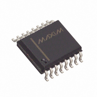
MAX807MEWE+ Maxim Integrated Products, MAX807MEWE+ Datasheet - Page 9

MAX807MEWE+
Manufacturer Part Number
MAX807MEWE+
Description
IC SUPERVISOR MPU 16-SOIC
Manufacturer
Maxim Integrated Products
Type
Battery Backup Circuitr
Datasheet
1.MAX807NEWE.pdf
(16 pages)
Specifications of MAX807MEWE+
Number Of Voltages Monitored
1
Reset
Active High/Active Low
Reset Timeout
140 ms Minimum
Voltage - Threshold
4.575V
Operating Temperature
-40°C ~ 85°C
Mounting Type
Surface Mount
Package / Case
16-SOIC (0.300", 7.5mm Width)
Monitored Voltage
4.425 V
Output Type
Active High, Active Low
Manual Reset
Resettable
Watchdog
Watchdog
Battery Backup Switching
Backup
Supply Voltage (max)
5.5 V
Supply Voltage (min)
0 V
Supply Current (typ)
70 uA
Maximum Power Dissipation
762 mW
Maximum Operating Temperature
+ 85 C
Mounting Style
SMD/SMT
Minimum Operating Temperature
- 40 C
Power Fail Detection
Yes
Undervoltage Threshold
4.35 V
Overvoltage Threshold
4.5 V
Power-up Reset Delay (typ)
280 ms
Lead Free Status / RoHS Status
Lead free / RoHS Compliant
Output
-
Lead Free Status / Rohs Status
Lead free / RoHS Compliant
Figure 2a. Timing Diagram, V
The RESET output is active low and implemented with a
strong pulldown/relatively weak pullup structure. It is
guaranteed to be a logic low for 0 < V
vided V
tery, RESET is guaranteed valid for V
sinks 3.2mA at 0.1V saturation voltage in its active state.
The RESET output is the inverse of the RESET output; it
both sources and sinks current and cannot be wire-OR
connected. Figure 2a shows a timing diagram with V
rising and Figure 2b shows V
Many µP-based products require manual-reset capabil-
ity to allow an operator or test technician to initiate a
reset. The Manual Reset (MR) input permits the genera-
tion of a reset in response to a logic low from a switch,
WDO, or external circuitry. Reset remains asserted
while MR is low, and for 200ms after MR returns high.
MR has an internal 50µA to 200µA pullup current, so it
can be left open if it is not used. MR can be driven with
TTL or CMOS-logic levels, or with open-drain/collector
outputs. Connect a normally open momentary switch
from MR to GND to create a manual-reset function;
external debounce circuitry is not required. If MR is dri-
ven from long cables or if the device is used in a noisy
environment, connect a 0.1µF capacitor from MR to
ground to provide additional noise immunity. As shown
in Figure 3, diode-ORed connections can be used to
allow manual resets from multiple sources. Figure 4
shows the reset timing.
(MAX801)
(MAX808)
V
LOW LINE
V
V
V
CE OUT
RESET
RESET
V
CC
BATT
SHOWN FOR V
V
BATT
is greater than 2V. Without a backup bat-
Full-Featured µP Supervisory Circuit with
V
RST
_______________________________________________________________________________________
CC
V
= 0 to 5V, V
LL
CC
Rising
BATT
CC
Manual Reset Input
t
t
RP
RP
= 2.8V, CE IN = GND
falling.
CC
CC
≥ 1. It typically
< V
RST
, pro-
CC
The watchdog circuit monitors the µP’s activity. If the
µP does not toggle the watchdog input (WDI) within
1.6s, WDO goes low. The internal 1.6s timer is cleared
and WDO returns high when reset is asserted or when
a transition (low-to-high or high-to-low) occurs at WDI
while RESET is high. As long as reset is asserted, the
timer remains cleared and does not count. As soon as
reset is released, the timer starts counting (Figure 5).
Supply current is typically reduced by 10µA when WDI
is at a valid logic level.
Figure 2b. Timing Diagram, V
Figure 3. Diode “OR” Connections Allow Multiple Reset
Sources to Connect to MR
±1.5% Reset Accuracy
V
LOW LINE
V
V
V
CE OUT
SOURCES
RESET
RESET
OTHER
RESET
V
CC
*DIODES NOT REQUIRED ON OPEN-DRAIN OUTPUTS.
MANUAL RESET
SHOWN FOR V
V
RST
+ V
LR
CC
V
= 5V to 0, V
RST
*
*
CC
Falling
BATT
V
BATT
= 2.8V, CE IN = GND
Watchdog Timer
MR
Watchdog Input
MAX807
9


