BH30RB1WGUT-E2 Rohm Semiconductor, BH30RB1WGUT-E2 Datasheet - Page 6
BH30RB1WGUT-E2
Manufacturer Part Number
BH30RB1WGUT-E2
Description
IC REG LDO 3.0V 150MA 4-VCSP
Manufacturer
Rohm Semiconductor
Specifications of BH30RB1WGUT-E2
Regulator Topology
Positive Fixed
Voltage - Output
3V
Voltage - Input
Up to 5.5V
Voltage - Dropout (typical)
0.1V @ 100mA
Number Of Regulators
1
Current - Output
150mA (Max)
Operating Temperature
-40°C ~ 85°C
Mounting Type
Surface Mount
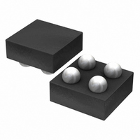
Package / Case
4-VCSP
Primary Input Voltage
4V
Output Voltage
3V
Dropout Voltage Vdo
25mV
No. Of Pins
4
Output Current
150mA
Voltage Regulator Case Style
VCSP
Operating Temperature Range
-40°C To +85°C
Svhc
No
Number Of Outputs
1
Polarity
Positive
Input Voltage Max
5.5 V
Output Type
Fixed
Dropout Voltage (max)
150 mV
Line Regulation
20 mV
Load Regulation
2 mV
Voltage Regulation Accuracy
1 %
Maximum Power Dissipation
0.53 W
Maximum Operating Temperature
+ 85 C
Mounting Style
SMD/SMT
Minimum Operating Temperature
- 40 C
Output Voltage Fixed
3V
Rohs Compliant
Yes
Lead Free Status / RoHS Status
Lead free / RoHS Compliant
Current - Limit (min)
-
Lead Free Status / Rohs Status
Lead free / RoHS Compliant
Other names
BH30RB1WGUT-E2TR
Available stocks
Company
Part Number
Manufacturer
Quantity
Price
Company:

Part Number:
BH30RB1WGUT-E2
Manufacturer:
ROHM
Quantity:
3 000


●Output capacitors
●Operation Notes
© 2011 ROHM Co., Ltd. All rights reserved.
BH□□RB1WGUT series
www.rohm.com
1. Absolute maximum ratings
2. Thermal design
3. Inter-pin shorts and mounting errors
4. Thermal shutdown circuit (TSD)
5. Overcurrent protection circuit
6. Actions in strong electromagnetic field
7. Ground wiring patterns
8. Influence of strong light
Mounting input capacitor between input pin and GND (as close to pin as possible), and also output capacitor between output
pin and GND(as close to pin as possible) is recommended. The input capacitor reduces the output impedance of the voltage
supply source connected to the VCC. The higher value the output capacitor goes the more stable the whole operation
becomes. This leads to high load transient response. Please confirm the whole operation on actual application board.
Generally, ceramic capacitor has wide range of tolerance, temperature coefficient, and DC bias characteristic. And also its value
goes lower as time progresses. Please choose ceramic capacitors after obtaining more detailed data by asking capacitor makers.
An excess in the absolute maximum ratings, such as supply voltage, temperature range of operating conditions, etc., can
break down the devices, thus making impossible to identify breaking mode, such as a short circuit or an open circuit. If any
over rated values will expect to exceed the absolute maximum ratings, consider adding circuit protection devices, such as
fuses.
Use a thermal design that allows for a sufficient margin in light of the power dissipation (Pd) in actual operating conditions.
Use caution when positioning the IC for mounting on printed circuit boards. The IC may be damaged if there is any
connection error or if pins are shorted together.
The IC incorporates a built-in thermal shutdown circuit (TSD circuit). The thermal shutdown circuit is designed only to shut
the IC off to prevent runaway thermal operation. It is not designed to protect the IC or guarantee its operation. Do not
continue to use the IC after operating this circuit or use the IC in an environment where the operation of this circuit is
assumed.
The IC incorporates a built-in overcurrent protection circuit that operates according to the output current capacity. This
circuit serves to protect the IC from damage when the load is shorted. The protection circuit is designed to limit current
flow by not latching in the event of a large and instantaneous current flow originating from a large capacitor or other
component. These protection circuits are effective in preventing damage due to sudden and unexpected accidents.
However, the IC should not be used in applications characterized by the continuous operation or transitioning of the
protection circuits. At the time of thermal designing, keep in mind that the current capability has negative characteristics to
temperatures.
When using both small signal and large current GND patterns, it is recommended to isolate the two ground patterns,
placing a single ground point at the ground potential of application so that the pattern wiring resistance and voltage
variations caused by large currents do not cause variations in the small signal ground voltage. Be careful not to change the
GND wiring pattern of any external components, either.
Exposure of the IC to strong light sources such as infrared light from a halogen lamp may cause the IC to malfunction.
When it is necessary to use the IC in such environments, implement measures to block exposure to light from the light
source. During testing, exposure to neither fluorescent lighting nor white LEDs had a significant effect on the IC.
Use caution when using the IC in the presence of a strong electromagnetic field as doing so may cause the IC to malfunction.
Fig. 29 Stable Operating Region Characteristics (Example)
0.01
100
0.1
10
1
0
BH□□RB1WGUT
Output Current Iout [mA]
出力電流 I
50
Stable region
OUT
6/8
[mA]
100
150
C
Ta = +25°C
OUT
= 1.0 µF
Technical Note
2011.01 - Rev.C
Related parts for BH30RB1WGUT-E2
Image
Part Number
Description
Manufacturer
Datasheet
Request
R

Part Number:
Description:
Manufacturer:
Rohm Semiconductor
Datasheet:
Part Number:
Description:
Manufacturer:
Rohm Semiconductor
Datasheet:
Part Number:
Description:
Manufacturer:
Rohm Semiconductor
Datasheet:
Part Number:
Description:
Manufacturer:
Rohm Semiconductor
Datasheet:
Part Number:
Description:
Manufacturer:
Rohm Semiconductor
Datasheet:
Part Number:
Description:
Manufacturer:
Rohm Semiconductor
Datasheet:
Part Number:
Description:
Manufacturer:
Rohm Semiconductor
Datasheet:
Part Number:
Description:
Manufacturer:
Rohm Semiconductor
Datasheet:
Part Number:
Description:
Manufacturer:
Rohm Semiconductor
Datasheet:
Part Number:
Description:
Manufacturer:
Rohm Semiconductor
Datasheet:
Part Number:
Description:
Manufacturer:
Rohm Semiconductor
Datasheet:
Part Number:
Description:
Manufacturer:
Rohm Semiconductor
Datasheet:

Part Number:
Description:
DIODE SWITCH 80V 25MA SMD5 TR
Manufacturer:
Rohm Semiconductor
Datasheet: