BH30RB1WGUT-E2 Rohm Semiconductor, BH30RB1WGUT-E2 Datasheet - Page 7
BH30RB1WGUT-E2
Manufacturer Part Number
BH30RB1WGUT-E2
Description
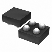
IC REG LDO 3.0V 150MA 4-VCSP
Manufacturer
Rohm Semiconductor
Specifications of BH30RB1WGUT-E2
Regulator Topology
Positive Fixed
Voltage - Output
3V
Voltage - Input
Up to 5.5V
Voltage - Dropout (typical)
0.1V @ 100mA
Number Of Regulators
1
Current - Output
150mA (Max)
Operating Temperature
-40°C ~ 85°C
Mounting Type
Surface Mount
Package / Case
4-VCSP
Primary Input Voltage
4V
Output Voltage
3V
Dropout Voltage Vdo
25mV
No. Of Pins
4
Output Current
150mA
Voltage Regulator Case Style
VCSP
Operating Temperature Range
-40°C To +85°C
Svhc
No
Number Of Outputs
1
Polarity
Positive
Input Voltage Max
5.5 V
Output Type
Fixed
Dropout Voltage (max)
150 mV
Line Regulation
20 mV
Load Regulation
2 mV
Voltage Regulation Accuracy
1 %
Maximum Power Dissipation
0.53 W
Maximum Operating Temperature
+ 85 C
Mounting Style
SMD/SMT
Minimum Operating Temperature
- 40 C
Output Voltage Fixed
3V
Rohs Compliant
Yes
Lead Free Status / RoHS Status
Lead free / RoHS Compliant
Current - Limit (min)
-
Lead Free Status / Rohs Status
Lead free / RoHS Compliant
Other names
BH30RB1WGUT-E2TR
Available stocks
Company
Part Number
Manufacturer
Quantity
Price
Company:

Part Number:
BH30RB1WGUT-E2
Manufacturer:
ROHM
Quantity:
3 000


© 2011 ROHM Co., Ltd. All rights reserved.
BH□□RB1WGUT series
www.rohm.com
9. GND voltage
10. Back Current
11. Testing on application boards
12. Regarding Input Pin of the IC (Fig.31)
The potential of GND pin must be minimum potential in all operating conditions.
In applications where the IC may be exposed to back current flow, it is recommended to create a path to dissipate this
current by inserting a bypass diode between the VIN and VOUT pins.
When testing the IC on an application board, connecting a capacitor to a pin with low impedance subjects the IC to stress.
Always discharge capacitors after each process or step. Always turn the IC's power supply off before connecting it to or
removing it from a jig or fixture during the inspection process. Ground the IC during assembly steps as an antistatic
measure. Use similar precaution when transporting or storing the IC.
This monolithic IC contains P+ isolation and P substrate layers between adjacent elements in order to keep them isolated.
P-N junctions are formed at the intersection of these P layers with the N layers of other elements, creating a parasitic diode
or transistor. For example, the relation between each potential is as follows:
Parasitic diodes can occur inevitable in the structure of the IC. The operation of parasitic diodes can result in mutual
interference among circuits, operational faults, or physical damage. Accordingly, methods by which parasitic diodes
operate, such as applying a voltage that is lower than the GND (P substrate) voltage to an input pin, should not be used.
Parasitic element
Pin A
N
P
+
When GND > Pin A and GND > Pin B, the P-N junction operates as a parasitic diode.
When GND > Pin B, the P-N junction operates as a parasitic transistor.
N
GND
P
P substrate
P
+
N
Resistor
Fig. 30 Example Bypass Diode Connection
Fig. 31
Pin A
Example of IC structure
Parasitic
element
VIN
STBY
GND
Parasitic element
Pin B
N
Back current
7/8
P
OUT
+
C
B
N
E
GND
P
P substrate
Transistor (NPN)
P
+
N
GND
Other adjacent elements
Pin B
B
Technical Note
2011.01 - Rev.C
C
E
GND
Parasitic
element
Related parts for BH30RB1WGUT-E2
Image
Part Number
Description
Manufacturer
Datasheet
Request
R

Part Number:
Description:
Manufacturer:
Rohm Semiconductor
Datasheet:
Part Number:
Description:
Manufacturer:
Rohm Semiconductor
Datasheet:
Part Number:
Description:
Manufacturer:
Rohm Semiconductor
Datasheet:
Part Number:
Description:
Manufacturer:
Rohm Semiconductor
Datasheet:
Part Number:
Description:
Manufacturer:
Rohm Semiconductor
Datasheet:
Part Number:
Description:
Manufacturer:
Rohm Semiconductor
Datasheet:
Part Number:
Description:
Manufacturer:
Rohm Semiconductor
Datasheet:
Part Number:
Description:
Manufacturer:
Rohm Semiconductor
Datasheet:
Part Number:
Description:
Manufacturer:
Rohm Semiconductor
Datasheet:
Part Number:
Description:
Manufacturer:
Rohm Semiconductor
Datasheet:
Part Number:
Description:
Manufacturer:
Rohm Semiconductor
Datasheet:
Part Number:
Description:
Manufacturer:
Rohm Semiconductor
Datasheet:

Part Number:
Description:
DIODE SWITCH 80V 25MA SMD5 TR
Manufacturer:
Rohm Semiconductor
Datasheet: