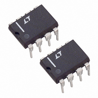
LT1175IN8 Linear Technology, LT1175IN8 Datasheet - Page 14

LT1175IN8
Manufacturer Part Number
LT1175IN8
Description
IC LDO REG ADJST NEG 500MA 8-DIP
Manufacturer
Linear Technology
Datasheet
1.LT1175CN8-5PBF.pdf
(20 pages)
Specifications of LT1175IN8
Regulator Topology
Negative Adjustable
Voltage - Output
-3.8 ~ -19.9 V
Voltage - Input
-4.3 ~ -20 V
Voltage - Dropout (typical)
0.5V @ 500mA
Number Of Regulators
1
Current - Output
500mA
Current - Limit (min)
Adjustable
Operating Temperature
-40°C ~ 85°C
Mounting Type
Through Hole
Package / Case
8-DIP (0.300", 7.62mm)
Lead Free Status / RoHS Status
Contains lead / RoHS non-compliant
Available stocks
Company
Part Number
Manufacturer
Quantity
Price
Company:
Part Number:
LT1175IN8-5
Manufacturer:
LT
Quantity:
14
LT1175
APPLICATIONS INFORMATION
To estimate regulator output ripple under different
conditions, the following general comments should be
helpful:
1. Output ripple at high frequency is only weakly affected
2. A feedforward capacitor across the resistor divider used
3. Input-to-output voltage differential has little effect on
If ripple rejection needs to be improved, an input fi lter can
be added. This fi lter can be a simple RC fi lter using a 1Ω
to 10Ω resistor. A 3.3Ω resistor for instance, combined
with a 0.3Ω ESR solid tantalum capacitor, will give an ad-
ditional 20dB ripple rejection. The size of the resistor will
be dictated by maximum load current. If the maximum
voltage drop allowable across the resistor is “V
maximum load current is I
14
by load current or output capacitor size for medium
to heavy loads. At very light loads (<10mA), higher
frequency ripple may be reduced by using larger output
capacitors.
with the adjustable part is effective in reducing ripple
only for output voltages greater than 5V and only for
frequencies less than 100kHz.
ripple rejection until the regulator actually enters a
dropout condition of 0.2V to 0.6V.
LOAD
, R = V
R
/I
LOAD
. At light
R
,” and
loads, larger resistors and smaller capacitors can be used
to save space. At heavier loads an inductor may have to
be used in place of the resistor. The value of the inductor
can be calculated from:
ESR = Effective series resistance of fi lter capacitor. This
f
rr
Example: ESR = 1.2Ω, f = 100kHz, rr = – 25dB.
Solid tantalum capacitors are suggested for the fi lter to
keep fi lter Q fairly low. This prevents unwanted ringing at
the resonant frequency of the fi lter and oscillation problems
with the fi lter/regulator combination.
L
L
FIL
FIL
= Ripple frequency
= Ripple rejection ratio of fi lter in dB
assumes that the capacitive reactance is small com-
pared to ESR, a reasonable assumption for solid
tantalum capacitors above 2.2μF and 50kHz.
=
=
2
6 3 10
π
.
( )
⎛
⎝
f
ESR
(
10
5
⎞
⎠
1 2
rr
⎛
⎝
.
10
/
20
−
)
25 20
/
⎞
⎠
=
34
μ
H
1175ff


