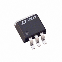
LT1585CM#TRPBF Linear Technology, LT1585CM#TRPBF Datasheet - Page 13

LT1585CM#TRPBF
Manufacturer Part Number
LT1585CM#TRPBF
Description
IC LDO REG 4.6A ADJ DDPAK-3
Manufacturer
Linear Technology
Datasheet
1.LT1585CT-3.3.pdf
(16 pages)
Specifications of LT1585CM#TRPBF
Regulator Topology
Positive Adjustable
Voltage - Output
1.25 ~ 5.5 V
Voltage - Input
2.35 ~ 7 V
Voltage - Dropout (typical)
1.2V @ 4A
Number Of Regulators
1
Current - Output
4.6A
Current - Limit (min)
4.1A
Operating Temperature
0°C ~ 125°C
Mounting Type
Surface Mount
Package / Case
TO-263-2, D⊃2Pak (2 leads + Tab), TO-263AB
Lead Free Status / RoHS Status
Lead free / RoHS Compliant
Available stocks
Company
Part Number
Manufacturer
Quantity
Price
APPLICATIONS
contribution to the total thermal resistance. Please consult
“Mounting Considerations for Power Semiconductors”
1990 Linear Applications Handbook, Volume I , Pages
RR3-1 to RR3-20. The output connects to the case of all
devices in the LT1584/LT1585/LT1587 series.
For example, using an LT1585CT-3.3 (TO-220, commer-
cial) and assuming:
Power dissipation under these conditions is equal to:
TYPICAL APPLICATIONS
486 and DX4 are trademarks of Intel Corporation.
4.75V TO
5.25V
V
I
T
P
OUT
A
CASE-TO-HEAT SINK
IN
D
= 70 C,
(Max Continuous) = 5.25V (5V + 5%), V
= (V
C1 TO C3
AVX TPS
= 4.6A
3 EACH
220 F
10V
IN
AVX X7R 0805
– V
+
HEAT SINK
OUT
Minimum Parts Count LT1585 Adjustable Circuit
330nF
V
16V
THERMALLOY
IN
IN
)(I
C4
U
7020B-MT
LT1585CT
Recommended LT1587-3.45 Circuit for the Intel 486
for the Intel Pentium VRE Processor
= 1 C/W (with Thermal Compound)
OUT
4.75V
ADJ
= 4 C/W
INFORMATION
) = (5.25 – 3.3)(4.6) = 9W
OUT
+
U
C1
10 F
10V
R1
110
0.1%
R2
197
0.1%
U
IN
LT1587-3.45
W
GND
AVX CORP. (803) 448-9411
THERMALLOY INC. (214) 243-4321
DO NOT SUBSTITUTE COMPONENTS.
N
+
OUT
PLACE IN MICROPROCESSOR
C5 TO C10
100 F
10V
AVX TPS
6 EACH
+
OUT
U
SOCKET CAVITY
C2
22 F
10V
= 3.3V,
ESR OF THE 47 F IS <0.1
+
PLACE AT MICROPROCESSOR SOCKET V
C11 TO C20
1 F
16V
AVX Y5V 0805
10 EACH
C3 TO C6
47 F
10V
3.50V
4.6A
Junction temperature will be equal to:
For the Control Section:
For the Power Transistor:
In both cases the junction temperature is below the maxi-
mum rating for the respective sections, ensuring reliable
operation.
1584/5/7 TA04
T
T
121.3 C < 125 C = T
range)
T
142 C < 150 C = T
Range)
J
J
J
= T
= 70 C + 9W (4 C/W + 1 C/W + 3 C/W) = 142 C
TM
= 70 C + 9W (4 C/W + 1 C/W + 0.7 C/W) = 121.3 C
C7 TO C15
0.1 F
DX4
A
+ P
TM
Overdrive Microprocessor
D
(
HEAT SINK
50mV/DIV
LT1584/LT1585/LT1587
C16 TO C24
0.01 F
2A/DIV
CC
V
I
3.45V
3A
OUT
OUT
JMAX
LT1584 • TA03
PINS
JMAX
*TRANSIENT RESPONSE MEASURED WITH AN INTEL
POWER VALIDATOR. V
POWER VALIDATOR
+
(Power Transistor Commercial
LT1585 Transient Response
for 3.8A Load Current Step*
(Control Section Commercial
CASE-TO-HEAT SINK
100 s/DIV
OUT
IS MEASURED AT THE
+
13
JC
158457a
LT1584 • TA05
)


