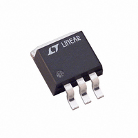
LT1585CM#TRPBF Linear Technology, LT1585CM#TRPBF Datasheet - Page 5

LT1585CM#TRPBF
Manufacturer Part Number
LT1585CM#TRPBF
Description
IC LDO REG 4.6A ADJ DDPAK-3
Manufacturer
Linear Technology
Datasheet
1.LT1585CT-3.3.pdf
(16 pages)
Specifications of LT1585CM#TRPBF
Regulator Topology
Positive Adjustable
Voltage - Output
1.25 ~ 5.5 V
Voltage - Input
2.35 ~ 7 V
Voltage - Dropout (typical)
1.2V @ 4A
Number Of Regulators
1
Current - Output
4.6A
Current - Limit (min)
4.1A
Operating Temperature
0°C ~ 125°C
Mounting Type
Surface Mount
Package / Case
TO-263-2, D⊃2Pak (2 leads + Tab), TO-263AB
Lead Free Status / RoHS Status
Lead free / RoHS Compliant
Available stocks
Company
Part Number
Manufacturer
Quantity
Price
temperature range, otherwise specifications are at T
Note 1: Absolute Maximum Ratings are those values beyond which the life
of a device may be impaired.
Note 2: See thermal regulation specifications for changes in output voltage
due to heating effects. Load and line regulation are measured at a constant
junction temperature by low duty cycle pulse testing.
Note 3: Line and load regulation are guaranteed up to the maximum power
dissipation (25W for the LT1584 in T package, 26.5W for the LT1585 in T
package, 18W for the LT1587 in T package). Power dissipation is
determined by input/output differential and the output current. Guaranteed
PARAMETER
Thermal Regulation
Temperature Stability
Long-Term Stability
RMS Output Noise
(% of V
Thermal Resistance
Junction to Case
ELECTRICAL CHARACTERISTICS
OUT
)
LT1584/5/7
LT1584/5/7-3.3
LT1584/5-3.38
LT1584/5/7-3.45 T
LT1584/5/7-3.6
LT1584
LT1585
LT1585
LT1587
LT1587
CONDITIONS
T
T
T
T Package: Control Circuitry/Power Transistor
M Package: Control Circuitry/Power Transistor
T Package: Control Circuitry/Power Transistor
T
T
T
T Package: Control Circuitry/Power Transistor
M Package: Control Circuitry/Power Transistor
A
A
A
A
A
A
A
= 25 C, 30ms pulse
= 25 C, 30ms pulse
= 25 C, 30ms pulse
= 25 C, 30ms pulse
= 25 C, 30ms pulse
= 125 C, 1000 Hrs.
= 25 C, 10Hz f 10kHz
A
= 25 C.
The
denotes the specifications which apply over the full operating
maximum output power will not be available over the full input/output
voltage range.
Note 4: I
as a function of input-to-output voltage. I
LT1584, 4.6A at T
and 3A for the LT1587. The remaining LT1585 fixed voltage versions are
4A. The LT1585 and LT1587 have constant current limit with changes in
input-to-output voltage. The LT1584 has variable current limit which
decreases about 4A as input-to-output voltage increases from 3V to 7V.
FULL LOAD
J
is defined as the maximum value of output load current
25 C and 4A at T
LT1584/LT1585/LT1587
MIN
J
< 25 C for the LT1585/LT1585-3.3
FULL LOAD
0.004
0.003
0.03
TYP
0.5
is equal to 7A for the
0.65/2.7
0.7/3.0
0.7/3.0
0.7/3.0
0.7/3.0
MAX
0.02
1.0
158457a
UNITS
%/W
5
C/W
C/W
C/W
C/W
C/W
%
%
%


