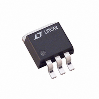
LT1585CM#TRPBF Linear Technology, LT1585CM#TRPBF Datasheet - Page 9

LT1585CM#TRPBF
Manufacturer Part Number
LT1585CM#TRPBF
Description
IC LDO REG 4.6A ADJ DDPAK-3
Manufacturer
Linear Technology
Datasheet
1.LT1585CT-3.3.pdf
(16 pages)
Specifications of LT1585CM#TRPBF
Regulator Topology
Positive Adjustable
Voltage - Output
1.25 ~ 5.5 V
Voltage - Input
2.35 ~ 7 V
Voltage - Dropout (typical)
1.2V @ 4A
Number Of Regulators
1
Current - Output
4.6A
Current - Limit (min)
4.1A
Operating Temperature
0°C ~ 125°C
Mounting Type
Surface Mount
Package / Case
TO-263-2, D⊃2Pak (2 leads + Tab), TO-263AB
Lead Free Status / RoHS Status
Lead free / RoHS Compliant
Available stocks
Company
Part Number
Manufacturer
Quantity
Price
APPLICATIONS
General
The LT1584/LT1585/LT1587 family of three-terminal
regulators is easy to use and has all the protection features
expected in high performance linear regulators. The de-
vices are short-circuit protected, safe-area protected, and
provide thermal shutdown to turn off the regulators
should the junction temperature exceed about 150 C. The
LT1584/LT1585/LT1587 family includes adjustable and
fixed voltage versions.
These ICs are pin compatible with the LT1083/LT1084/
LT1085 family of linear regulators but offer lower dropout
voltage and faster transient response. The trade-off for this
improved performance is a 7V maximum supply voltage.
Similar to the LT1083/LT1084/LT1085 family, the LT1584/
LT1585/LT1587 regulators require an output capacitor for
stability. However, the improved frequency compensation
permits the use of capacitors with much lower ESR while still
maintaining stability. This is critical in addressing the needs
of modern, low voltage, high speed microprocessors.
Current generation microprocessors cycle load current
from almost zero to amps in tens of nanoseconds. Output
voltage tolerances are tighter and include transient re-
sponse as part of the specification. The LT1584/LT1585/
LT1587 family is specifically designed to meet the fast
current load-step requirements of these microprocessors
and saves total cost by needing less output capacitance in
order to maintain regulation.
Stability
The circuit design in the LT1584/LT1585/LT1587 family
requires the use of an output capacitor as part of the
frequency compensation. For all operating conditions, the
addition of a 22 F solid tantalum or a 100 F aluminum
electrolytic on the output ensures stability. Normally, the
LT1584/LT1585/LT1587 can use smaller value capacitors.
Many different types of capacitors are available and have
widely varying characteristics. These capacitors differ in
capacitor tolerance (sometimes ranging up to 100%),
equivalent series resistance, equivalent series inductance,
and capacitance temperature coefficient. The LT1584/
U
INFORMATION
U
W
U
LT1585/LT1587 frequency compensation optimizes fre-
quency response with low ESR capacitors. In general, use
capacitors with an ESR of less than 1 .
On the adjustable LT1584/LT1585/LT1587, bypassing the
adjust terminal improves ripple rejection and transient
response. Bypassing the adjust pin increases the required
output capacitor value. The value of 22 F tantalum or
100 F aluminum covers all cases of bypassing the adjust
terminal. With no adjust pin bypassing, smaller values of
capacitors provide equally good results.
Normally, capacitor values on the order of several hundred
microfarads are used on the output of the regulators to
ensure good transient response with heavy load current
changes. Output capacitance can increase without limit
and larger values of output capacitance further improve the
stability and transient response of the LT1584/LT1585/
LT1587 family.
Large load current changes are exactly the situation pre-
sented by modern microprocessors. The load current step
contains higher order frequency components that the
output decoupling network must handle until the regulator
throttles to the load current level. Capacitors are not ideal
elements and contain parasitic resistance and inductance.
These parasitic elements dominate the change in output
voltage at the beginning of a transient load step change.
The ESR of the output capacitors produces an instanta-
neous step in output voltage ( V = I ESR). The ESL of
the output capacitors produces a droop proportional to the
rate of change of output current (V = L
capacitance produces a change in output voltage propor-
tional to the time until the regulator can respond ( V = t
I/C). These transient effects are illustrated in Figure 1.
ESR
EFFECTS
ESL
EFFECTS
SLOPE,
V
t
=
LT1584/LT1585/LT1587
C
I
Figure 1
POINT AT WHICH REGULATOR
TAKES CONTROL
I/ t). The output
CAPACITANCE
EFFECTS
158457a
LT1584 • F01
9


