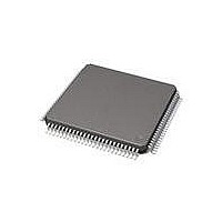
71M6513-IGT/F Maxim Integrated Products, 71M6513-IGT/F Datasheet - Page 48

71M6513-IGT/F
Manufacturer Part Number
71M6513-IGT/F
Description
IC ENERGY METER 3PH 100-LQFP
Manufacturer
Maxim Integrated Products
Datasheet
1.71M6513H-IGTF.pdf
(104 pages)
Specifications of 71M6513-IGT/F
Mounting Style
SMD/SMT
Package / Case
LQFP-100
Program Memory Size
64 KB
Program Memory Type
Flash
Supply Current (max)
6.4 mA
Lead Free Status / RoHS Status
Lead free / RoHS Compliant
Available stocks
Company
Part Number
Manufacturer
Quantity
Price
Company:
Part Number:
71M6513-IGT/F
Manufacturer:
MAXIM
Quantity:
1 300
Company:
Part Number:
71M6513-IGT/F
Manufacturer:
Maxim Integrated
Quantity:
10 000
Part Number:
71M6513-IGT/F
Manufacturer:
MAXIM/美信
Quantity:
20 000
out in 35 cycles and contains a leading flag bit. Figure 13 in the System Timing Section illustrates the RTM output format. RTM
is low when not in use.
SSI Interface: A high-speed serial interface with handshake capability is available to send a contiguous block of CE data to an
external data logger or DSP. The block of data, configurable as to location and size, is sent starting 1 cycle of 32kHz before
each CE code pass begins. If the block of data is big enough that transmission has not completed when the code pass begins,
it will complete during the CE code pass with no timing impact to the CE or the serial data. In this case, care must be taken
that the transmitted data is not modified unexpectedly by the CE. The SSI interface is enabled by the SSI_EN bit and consists
of SCLK, SSDATA, and SFR as outputs and, optionally, SRDY as input. The interface is compatible with 16bit and 32bit
processors. The operation of each pin is as follows:
SCLK is the serial clock. The clock can be 5MHz or 10MHz, as specified by the SSI_10M bit. The SSI_CKGATE bit controls
whether SCLK runs continuously or is gated off when no SSI activity is occurring. If SCLK is gated, it will begin 3 cycles before
SFR rises and will persist 3 cycles after the last data bit is output.
The pins used for the SSI are multiplexed with the LCD segment outputs, as shown in Table 58. Thus, the LCD should be
disabled when the SSI is in use.
SRDY is an optional handshake input that indicates that the DSP or data-logging device is ready to receive data. SRDY must
be true (the polarity of SRDY is selectable with SSI_FPOL) to enable SFR to rise and initiate the transfer of the next field. It is
expected that SRDY changes state on the rising edges of SCLK. If SRDY is not true when the SSI port is ready to transmit the
next field, transmission will be delayed until it is. SRDY is ignored except at the beginning of a field transmission. If SRDY is
not enabled (by SSI_RDYEN), the SSI port will behave as if SRDY is always true.
SSDATA is the serial output data. SSDATA changes on the rising edge of SCLK and outputs the contents of a block of CE
RAM words starting with address SSI_STRT and ending with SSI_END. The words are output MSB first.
The field size is set with the SSI_FSIZE register: 0 entire data block, 1-8 bit fields, 2-16 bit fields, 3-32 bit fields. The polarity of
the SFR pulse can be inverted with SSI_FPOL (SSI_FPOL = 0 SRDY high-active). If SRDY does not delay it, the first SFR
pulse in a frame will rise on the third SCLK after MUX_SYNC (or the fourth SCLK if 10MHz). MUX_SYNC can be used to
synchronize the fields arriving at the data logger or DSP.
Page: 48 of 104
A Maxim Integrated Products Brand
© 2005-2011 Teridian Semiconductor Corporation
SSI Signal
SSDATA
Table 58: SSI Pin Assignment
SRDY
SCLK
SFR
3-Phase Energy Meter IC
LCD Segment
Output Pin
SEG3
SEG4
SEG5
SEG6
71M6513/71M6513H
DATA SHEET
AUGUST 2011


