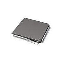
71M6513-IGT/F Maxim Integrated Products, 71M6513-IGT/F Datasheet - Page 6

71M6513-IGT/F
Manufacturer Part Number
71M6513-IGT/F
Description
IC ENERGY METER 3PH 100-LQFP
Manufacturer
Maxim Integrated Products
Datasheet
1.71M6513H-IGTF.pdf
(104 pages)
Specifications of 71M6513-IGT/F
Mounting Style
SMD/SMT
Package / Case
LQFP-100
Program Memory Size
64 KB
Program Memory Type
Flash
Supply Current (max)
6.4 mA
Lead Free Status / RoHS Status
Lead free / RoHS Compliant
Available stocks
Company
Part Number
Manufacturer
Quantity
Price
Company:
Part Number:
71M6513-IGT/F
Manufacturer:
MAXIM
Quantity:
1 300
Company:
Part Number:
71M6513-IGT/F
Manufacturer:
Maxim Integrated
Quantity:
10 000
Part Number:
71M6513-IGT/F
Manufacturer:
MAXIM/美信
Quantity:
20 000
Tables
Page: 6 of 104
Figure 34: Error Band for VREF over Temperature (High-Accuracy Parts) ..................................................................... 83
Figure 33: Connecting LCDs ...................................................................................................................................... 84
Figure 34: LCD Boost Circuit...................................................................................................................................... 85
Figure 35: EEPROM Connection ................................................................................................................................. 85
Figure 36: Interfacing RX to a 0-5V Signal .................................................................................................................. 86
Figure 37: Connection for Optical Components ........................................................................................................... 87
Figure 38: Voltage Divider for V1 ............................................................................................................................... 87
Figure 39: External Components for RESETZ .............................................................................................................. 88
Table 1: Inputs Selected in Regular and Alternate Multiplexer Cycles.......................................................... 9
Table 2: CE DRAM Locations for ADC Results ......................................................................................... 12
Table 3: Standard Meter Equations (inputs shown gray are scanned but not used for calculation) .............. 13
Table 4: Stretch Memory Cycle Width ...................................................................................................... 17
Table 5: Internal Data Memory Map ......................................................................................................... 18
Table 6: Special Function Registers Locations ......................................................................................... 18
Table 7: Special Function Registers Reset Values .................................................................................... 20
Table 8: PSW Register Flags ................................................................................................................... 20
Table 9: PSW bit functions ...................................................................................................................... 21
Table 10: Port Registers .......................................................................................................................... 22
Table 11: Special Function Registers ....................................................................................................... 23
Table 12: Baud Rate Generation.............................................................................................................. 24
Table 13: UART Modes ........................................................................................................................... 24
Table 14: The S0CON Register ................................................................................................................. 24
Table 15: The S1CON register .................................................................................................................. 25
Table 16: The S0CON Bit Functions.......................................................................................................... 25
Table 17: The S1CON Bit Functions.......................................................................................................... 26
Table 18: The TMOD Register ................................................................................................................. 26
Table 19: TMOD Register Bit Description ................................................................................................. 27
Table 20: Timers/Counters Mode Description ........................................................................................... 27
Table 21: The TCON Register .................................................................................................................. 27
Table 22: The TCON Register Bit Functions ............................................................................................. 28
Table 23: Timer Modes............................................................................................................................ 28
Table 24: The PCON Register ................................................................................................................. 28
Table 25: The IEN0 Register (see also Table 32) ...................................................................................... 29
Table 26: The IEN0 Bit Functions (see also Table 32) ............................................................................... 29
Table 27: The IEN1 Register (see also Tables 30/31) ............................................................................... 29
Table 28: The IEN1 Bit Functions (see also Tables 30/31) ........................................................................ 29
Table 29: The IP0 Register (see also Table 45) ........................................................................................ 30
Table 30: The IP0 bit Functions (see also Table 45) ................................................................................. 30
Table 31: The WDTREL Register ............................................................................................................. 30
Table 32: The WDTREL Bit Functions ...................................................................................................... 30
Table 33: The IEN0 Register .................................................................................................................... 32
Table 34: The IEN0 Bit Functions ............................................................................................................. 32
Table 35: The IEN1 Register ................................................................................................................... 32
Table 36: The IEN1 Bit Functions ............................................................................................................ 32
Table 37: The IEN2 Register ................................................................................................................... 33
Table 38: The IEN2 Bit Functions ............................................................................................................ 33
A Maxim Integrated Products Brand
© 2005-2011 Teridian Semiconductor Corporation
3-Phase Energy Meter IC
71M6513/71M6513H
DATA SHEET
AUGUST 2011


