EVAL6229QR STMicroelectronics, EVAL6229QR Datasheet - Page 16
EVAL6229QR
Manufacturer Part Number
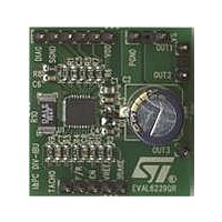
EVAL6229QR
Description
BOARD DEMO L6229Q BLDC MOT CTRL
Manufacturer
STMicroelectronics
Type
Motor / Motion Controllers & Driversr
Specifications of EVAL6229QR
Main Purpose
Power Management, Motor Control
Embedded
No
Utilized Ic / Part
L6229Q
Primary Attributes
3-Ph BLDC, 8 ~ 52V Output, PWM Current Control, Brake Function
Secondary Attributes
Over Current, Cross Conduction & Temperature Protection
Maximum Operating Temperature
+ 125 C
Operating Supply Voltage
8 V to 52 V
Product
Power Management Development Tools
Lead Free Status / RoHS Status
Lead free / RoHS Compliant
For Use With/related Products
L6229Q
Other names
497-10748


Circuit description
5.4
5.5
16/28
Slow decay mode
Figure 13
any time only two legs of the three-phase bridge are active, therefore only the two active
legs of the bridge are shown in the figure and the third leg will be off. At the start of the Off
Time, the lower power MOS is switched off and the current recirculates around the upper
half of the bridge. Since the voltage across the coil is low, the current decays slowly. After
the dead time the upper power MOS is operated in the synchronous rectification mode
reducing the impedance of the freewheeling diode and the related conducting losses. When
the monostable times out, upper MOS that was operating the synchronous mode turns off
and the lower power MOS is turned on again after some delay set by the dead time to
prevent cross conduction.
Figure 13. Slow decay mode output stage configurations
Decoding logic
The decoding logic section is a combinatory logic that provides the appropriate driving of the
three-phase bridge outputs according to the signals coming from the three hall sensors that
detect rotor position in a 3-phase BLDC motor. This novel combinatory logic discriminates
between the actual sensor positions for sensors spaced at 60, 120, 240 and 300 electrical
degrees. This decoding method allows the implementation of a universal IC without
dedicating pins to select the sensor configuration.
There are eight possible input combinations for three sensor inputs. Six combinations are
valid for rotor positions with 120 electrical degrees sensor phasing (see
1, 2, 3a, 4, 5 and 6a) and six combinations are valid for rotor positions with 60 electrical
degrees phasing (see
common (1, 2, 4 and 5) whereas there are two combinations used only in 120 electrical
degrees sensor phasing (3a and 6a) and two combinations used only in 60 electrical
degrees sensor phasing (3b and 6b).
The decoder can drive motors with different sensor configuration simply by following the
Table
OUT
configuration 6a is the same than 6b.
The sequence of the Hall codes for 300 electrical degrees phasing is the reverse of 60 and
the sequence of the Hall codes for 240 phasing is the reverse of 120. So, by decoding the 60
2
8. For any input configuration (H
A) ON TIME
and OUT
shows the operation of the bridge in the slow decay mode during the off time. At
3
). The output configuration 3a is the same than 3b and analogously output
D01IN1336
Figure
B) 1μs DEAD TIME
15, positions 1, 2, 3b, 4, 5 and 6b). Four of them are in
Doc ID 15209 Rev 3
1
, H
2
and H
3
) there is one output configuration (OUT
C) SYNCHRONOUS
RECTIFICATION
Figure
D) 1μs DEAD TIME
14, positions
L6229Q
1
,
Related parts for EVAL6229QR
Image
Part Number
Description
Manufacturer
Datasheet
Request
R

Part Number:
Description:
ENERCHIP CC EVAL KIT
Manufacturer:
Cymbet Corporation
Datasheet:

Part Number:
Description:
BOARD EVAL FOR AD976
Manufacturer:
Analog Devices Inc
Datasheet:

Part Number:
Description:
BOARD EVAL FOR ADXL345
Manufacturer:
Analog Devices Inc
Datasheet:

Part Number:
Description:
ENERCHIP CC SEH EVAL KIT
Manufacturer:
Cymbet Corporation
Datasheet:

Part Number:
Description:
ENERCHIP EP ENERGY HARVEST EVAL
Manufacturer:
Cymbet Corporation
Datasheet:

Part Number:
Description:
EVAL BOARD FOR TW6864-LB2-GR
Manufacturer:
Intersil
Datasheet:
Part Number:
Description:
EVAL BOARD FOR TW8816-LB3-GR
Manufacturer:
Intersil
Datasheet:
Part Number:
Description:
EVAL BOARD FOR TW8817-TA3-GRS
Manufacturer:
Intersil
Datasheet:

Part Number:
Description:
EVALUATION MODULE FOR ADUM4160
Manufacturer:
Analog Devices Inc
Datasheet:

Part Number:
Description:
BOARD EVALUATION ADCMP581BCP
Manufacturer:
Analog Devices Inc
Datasheet:
Part Number:
Description:
BOARD EVALUATION ADM1041
Manufacturer:
Analog Devices Inc
Datasheet:

Part Number:
Description:
EVAL BOARD FOR STM32F107VCT
Manufacturer:
STMicroelectronics
Datasheet:
Part Number:
Description:
BOARD EVAL FOR AD1954
Manufacturer:
Analog Devices Inc
Datasheet:
Part Number:
Description:
BOARD EVAL FOR AD1955
Manufacturer:
Analog Devices Inc
Datasheet:

Part Number:
Description:
BOARD EVAL FOR AD7655
Manufacturer:
Analog Devices Inc
Datasheet: