EVAL6229QR STMicroelectronics, EVAL6229QR Datasheet - Page 7
EVAL6229QR
Manufacturer Part Number
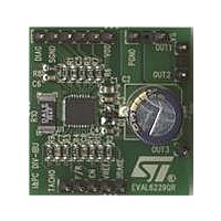
EVAL6229QR
Description
BOARD DEMO L6229Q BLDC MOT CTRL
Manufacturer
STMicroelectronics
Type
Motor / Motion Controllers & Driversr
Specifications of EVAL6229QR
Main Purpose
Power Management, Motor Control
Embedded
No
Utilized Ic / Part
L6229Q
Primary Attributes
3-Ph BLDC, 8 ~ 52V Output, PWM Current Control, Brake Function
Secondary Attributes
Over Current, Cross Conduction & Temperature Protection
Maximum Operating Temperature
+ 125 C
Operating Supply Voltage
8 V to 52 V
Product
Power Management Development Tools
Lead Free Status / RoHS Status
Lead free / RoHS Compliant
For Use With/related Products
L6229Q
Other names
497-10748


L6229Q
Table 5.
1, 21
N°
11
12
13
14
15
16
17
19
20
22
23
24
25
26
27
28
29
30
31
9
RCPULSE
FWD/REV
SENSE
SENSE
BRAKE
VBOOT
RCOFF
TACHO
VREF
OUT
OUT
OUT
DIAG
GND
VCP
VS
VS
Pin
Pin description
EN
H
H
H
2
3
1
B
A
3
2
1
B
A
Power supply
Power supply
Power supply
Power supply
Power output Output half bridge 3.
Power output Output half bridge 2.
Power output Output half bridge 1.
Sensor input Single ended hall effect sensor input 2.
Sensor input Single ended hall effect sensor input 3.
Sensor input Single ended hall effect sensor input 1.
Open drain
Open drain
Logic input
Logic input
Logic input
Logic input
voltage
RC pin
Supply
Output
RC pin
output
output
Type
GND
Ground terminals.
Frequency-to-voltage open drain output. Every pulse from pin H
as a fixed and adjustable length pulse.
RC network pin. A parallel RC network connected between this pin and
ground sets the duration of the monostable pulse used for the frequency-to-
voltage converter.
Half bridge 3 source Pin. This pin must be connected together with pin
SENSE
the Inverting Input of the sense comparator is connected.
Selects the direction of the rotation. HIGH logic level sets forward operation,
whereas LOW logic level sets reverse operation.
If not used, it has to be connected to GND or +5 V.
Chip enable. LOW logic level switches OFF all power MOSFETs.
If not used, it has to be connected to +5 V.
Current controller reference voltage.
Do not leave this pin open or connect to GND.
Brake input pin. LOW logic level switches ON all high side power MOSFETs,
implementing the brake function.
If not used, it has to be connected to +5 V.
Bootstrap voltage needed for driving the upper power MOSFETs.
Half bridge 3 power supply voltage. It must be connected to the supply
voltage together with pin VS
Half bridge 1 and half bridge 2 power supply voltage. It must be connected to
the supply voltage together with pin VS
Charge pump oscillator output.
Overcurrent detection and thermal protection pin. An internal open drain
transistor pulls to GND when an overcurrent on one of the high side
MOSFETs is detected or during thermal protection.
Half bridge 1 and half bridge 2 source pin. This pin must be connected
together with pin SENSE
RC network pin. A parallel RC network connected between this pin and
ground sets the current controller OFF-Time.
A
to power ground through a sensing power resistor. At this pin also
Doc ID 15209 Rev 3
B
to power ground through a sensing power resistor.
A
.
Function
B
.
Pin connection
1
is shaped
7/28
Related parts for EVAL6229QR
Image
Part Number
Description
Manufacturer
Datasheet
Request
R

Part Number:
Description:
ENERCHIP CC EVAL KIT
Manufacturer:
Cymbet Corporation
Datasheet:

Part Number:
Description:
BOARD EVAL FOR AD976
Manufacturer:
Analog Devices Inc
Datasheet:

Part Number:
Description:
BOARD EVAL FOR ADXL345
Manufacturer:
Analog Devices Inc
Datasheet:

Part Number:
Description:
ENERCHIP CC SEH EVAL KIT
Manufacturer:
Cymbet Corporation
Datasheet:

Part Number:
Description:
ENERCHIP EP ENERGY HARVEST EVAL
Manufacturer:
Cymbet Corporation
Datasheet:

Part Number:
Description:
EVAL BOARD FOR TW6864-LB2-GR
Manufacturer:
Intersil
Datasheet:
Part Number:
Description:
EVAL BOARD FOR TW8816-LB3-GR
Manufacturer:
Intersil
Datasheet:
Part Number:
Description:
EVAL BOARD FOR TW8817-TA3-GRS
Manufacturer:
Intersil
Datasheet:

Part Number:
Description:
EVALUATION MODULE FOR ADUM4160
Manufacturer:
Analog Devices Inc
Datasheet:

Part Number:
Description:
BOARD EVALUATION ADCMP581BCP
Manufacturer:
Analog Devices Inc
Datasheet:
Part Number:
Description:
BOARD EVALUATION ADM1041
Manufacturer:
Analog Devices Inc
Datasheet:

Part Number:
Description:
EVAL BOARD FOR STM32F107VCT
Manufacturer:
STMicroelectronics
Datasheet:
Part Number:
Description:
BOARD EVAL FOR AD1954
Manufacturer:
Analog Devices Inc
Datasheet:
Part Number:
Description:
BOARD EVAL FOR AD1955
Manufacturer:
Analog Devices Inc
Datasheet:

Part Number:
Description:
BOARD EVAL FOR AD7655
Manufacturer:
Analog Devices Inc
Datasheet: