TWR-MCF51JE-KIT Freescale Semiconductor, TWR-MCF51JE-KIT Datasheet - Page 2
TWR-MCF51JE-KIT
Manufacturer Part Number
TWR-MCF51JE-KIT
Description
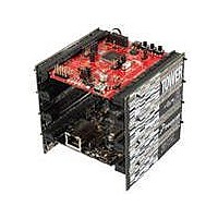
TOWER SYSTEM KIT MCF51JE
Manufacturer
Freescale Semiconductor
Series
ColdFire®, Flexis™r
Type
MCUr
Specifications of TWR-MCF51JE-KIT
Contents
4 Boards, Cables, Documentation, DVD
Data Bus Width
32 bit
Interface Type
RS-232, RS-485, Ethernet, CAN, USB
Silicon Manufacturer
Freescale
Core Architecture
Coldfire
Core Sub-architecture
Coldfire V1
Silicon Core Number
MCF51J
Silicon Family Name
Flexis - MCF51JE
Rohs Compliant
Yes
For Use With/related Products
Freescale Tower System, MCF51JE
Lead Free Status / RoHS Status
Lead free / RoHS Compliant


List of Topics
List of Figures
1-2
Figure 1. MCF51JE256/128 Block Diagram. . . . . . . . . . . . . . . . . 3
Figure 2. 104-Pin MAPBGA . . . . . . . . . . . . . . . . . . . . . . . . . . . . . 7
Figure 3. 100-Pin LQFP . . . . . . . . . . . . . . . . . . . . . . . . . . . . . . . . 8
Figure 4. 81-Pin MAPBGA . . . . . . . . . . . . . . . . . . . . . . . . . . . . . . 9
Figure 5. 80-Pin LQFP . . . . . . . . . . . . . . . . . . . . . . . . . . . . . . . . 10
Figure 6. Stop IDD versus Temperature. . . . . . . . . . . . . . . . . . . 26
Figure 7. Offset at Half Scale vs Temperature . . . . . . . . . . . . . . 28
Figure 8. ADC Input Impedance Equivalency Diagram . . . . . . . 30
Figure 9. Mini-FlexBus Read Timing . . . . . . . . . . . . . . . . . . . . . 36
Figure 10.Mini-FlexBus Write Timing . . . . . . . . . . . . . . . . . . . . 36
Figure 11.Reset Timing . . . . . . . . . . . . . . . . . . . . . . . . . . . . . . . 38
Figure 12.IRQ/KBIPx Timing . . . . . . . . . . . . . . . . . . . . . . . . . . . 38
Figure 13.Timer External Clock . . . . . . . . . . . . . . . . . . . . . . . . . 39
2.1
2.2
2.3
2.4
2.5
3.1
3.2
3.3
3.4
3.5
3.6
3.7
3.8
3.9
3.10 MCG and External Oscillator (XOSC) Characteristics .33
3.11 Mini-FlexBus Timing Specifications . . . . . . . . . . . . . . .35
3.12 AC Characteristics . . . . . . . . . . . . . . . . . . . . . . . . . . . .37
3.13 SPI Characteristics . . . . . . . . . . . . . . . . . . . . . . . . . . . .40
3.14 Flash Specifications . . . . . . . . . . . . . . . . . . . . . . . . . . .44
3.15 USB Electricals . . . . . . . . . . . . . . . . . . . . . . . . . . . . . . .45
3.16 VREF Electrical Specifications . . . . . . . . . . . . . . . . . . .46
4.1
4.2
4.3
104-Pin MAPBGA . . . . . . . . . . . . . . . . . . . . . . . . . . . . . .7
100-Pin LQFP . . . . . . . . . . . . . . . . . . . . . . . . . . . . . . . . .8
81-Pin MAPBGA . . . . . . . . . . . . . . . . . . . . . . . . . . . . . . .9
80-Pin LQFP . . . . . . . . . . . . . . . . . . . . . . . . . . . . . . . . .10
Pin Assignments . . . . . . . . . . . . . . . . . . . . . . . . . . . . . .11
Parameter Classification . . . . . . . . . . . . . . . . . . . . . . . .15
Absolute Maximum Ratings . . . . . . . . . . . . . . . . . . . . .16
Thermal Characteristics . . . . . . . . . . . . . . . . . . . . . . . .17
ESD Protection Characteristics. . . . . . . . . . . . . . . . . . .18
DC Characteristics . . . . . . . . . . . . . . . . . . . . . . . . . . . .19
Supply Current Characteristics . . . . . . . . . . . . . . . . . . .23
PRACMP Electricals . . . . . . . . . . . . . . . . . . . . . . . . . . .26
12-bit DAC Electricals . . . . . . . . . . . . . . . . . . . . . . . . . .27
ADC Characteristics . . . . . . . . . . . . . . . . . . . . . . . . . . .29
3.12.1 Control Timing . . . . . . . . . . . . . . . . . . . . . . . . . .37
3.12.2 TPM Timing . . . . . . . . . . . . . . . . . . . . . . . . . . . .39
Part Numbers . . . . . . . . . . . . . . . . . . . . . . . . . . . . . . . .48
Package Information . . . . . . . . . . . . . . . . . . . . . . . . . . .48
Mechanical Drawings . . . . . . . . . . . . . . . . . . . . . . . . . .49
Table of Contents
Preliminary — Subject to Change
List of Tables
Figure 14.Timer Input Capture Pulse . . . . . . . . . . . . . . . . . . . . . 39
Figure 15.SPI Master Timing (CPHA = 0) . . . . . . . . . . . . . . . . . 42
Figure 16.SPI Master Timing (CPHA = 1) . . . . . . . . . . . . . . . . . 42
Figure 17.SPI Slave Timing (CPHA = 0) . . . . . . . . . . . . . . . . . . 43
Figure 18.SPI Slave Timing (CPHA = 1) . . . . . . . . . . . . . . . . . . 43
Figure 19.Typical Output vs. Temperature . . . . . . . . . . . . . . . . . 47
Figure 20.Typical Output vs. V
Table 1. MCF51JE256/128 Features by MCU and Package . . . 4
Table 2. MCF51JE256/128 Functional Units. . . . . . . . . . . . . . . . 5
Table 3. Package Pin Assignments . . . . . . . . . . . . . . . . . . . . . . 11
Table 4. Parameter Classifications . . . . . . . . . . . . . . . . . . . . . . 15
Table 5. Absolute Maximum Ratings. . . . . . . . . . . . . . . . . . . . . 16
Table 6. Thermal Characteristics. . . . . . . . . . . . . . . . . . . . . . . . 17
Table 7. ESD and Latch-up Test Conditions . . . . . . . . . . . . . . . 18
Table 8. ESD and Latch-Up Protection Characteristics. . . . . . . 18
Table 9. DC Characteristics. . . . . . . . . . . . . . . . . . . . . . . . . . . . 19
Table 10.Supply Current Characteristics . . . . . . . . . . . . . . . . . . 23
Table 11.Typical Stop Mode Adders. . . . . . . . . . . . . . . . . . . . . . 25
Table 12.PRACMP Electrical Specifications . . . . . . . . . . . . . . . 26
Table 13.DAC 12LV Operating Requirements . . . . . . . . . . . . . . 27
Table 14.DAC 12-Bit Operating Behaviors . . . . . . . . . . . . . . . . . 28
Table 15.12-bit ADC Operating Conditions . . . . . . . . . . . . . . . . 29
Table 16.12-bit SAR ADC Characteristics full operating range
Table 17.MCG (Temperature Range = –40 to 105°C Ambient) . 33
Table 18.XOSC (Temperature Range = –40 to 105°C Ambient) 34
Table 19.Mini-FlexBus AC Timing Specifications . . . . . . . . . . . . 35
Table 20.Control Timing . . . . . . . . . . . . . . . . . . . . . . . . . . . . . . . 37
Table 21.TPM Input Timing . . . . . . . . . . . . . . . . . . . . . . . . . . . . 39
Table 22.SPI Timing . . . . . . . . . . . . . . . . . . . . . . . . . . . . . . . . . 40
Table 23.SPI Electrical Characteristic . . . . . . . . . . . . . . . . . . . 41
Table 24.Flash Characteristics . . . . . . . . . . . . . . . . . . . . . . . . . . 44
Table 25.Internal USB 3.3 V Voltage Regulator Characteristics 45
Table 26.VREF Electrical Specifications . . . . . . . . . . . . . . . . . 46
Table 27.VREF Limited Range Operating Requirements. . . . . . 46
Table 28.VREF Limited Range Operating Behaviors . . . . . . . . . 46
Table 29.Orderable Part Number Summary. . . . . . . . . . . . . . . . 48
Table 30.Package Descriptions . . . . . . . . . . . . . . . . . . . . . . . . . 48
Table 31.Revision History. . . . . . . . . . . . . . . . . . . . . . . . . . . . . . 49
(VREFH = VDDAD, > 1.8, VREFL = VSSAD ≤ 8 MHz) 31
DD
. . . . . . . . . . . . . . . . . . . . . . . . 47
Freescale Semiconductor
Related parts for TWR-MCF51JE-KIT
Image
Part Number
Description
Manufacturer
Datasheet
Request
R

Part Number:
Description:
LCD MODULE FOR TWR SYSTEM
Manufacturer:
Freescale Semiconductor
Datasheet:

Part Number:
Description:
TOWER ELEVATOR BOARDS HARDWARE
Manufacturer:
Freescale Semiconductor
Datasheet:

Part Number:
Description:
TOWER SERIAL I/O HARDWARE
Manufacturer:
Freescale Semiconductor
Datasheet:

Part Number:
Description:
MEMORY MODULE FOR TWR SYSTEM
Manufacturer:
Freescale Semiconductor
Datasheet:

Part Number:
Description:
MCU, MPU & DSP Development Tools TOWER CD MCF51AG128 KIT
Manufacturer:
Freescale Semiconductor

Part Number:
Description:
TOWER SYSTEM SENSOR PAK
Manufacturer:
Freescale Semiconductor
Datasheet:

Part Number:
Description:
KIT TOWER BOARD/SERIAL/ELEVATOR
Manufacturer:
Freescale Semiconductor
Datasheet:

Part Number:
Description:
KIT TOWER BOARD
Manufacturer:
Freescale Semiconductor
Datasheet:

Part Number:
Description:
TOWER SYSTEM BOARD MC9S08MM128
Manufacturer:
Freescale Semiconductor
Datasheet:

Part Number:
Description:
TOWER SYSTEM BOARD MCF51MM
Manufacturer:
Freescale Semiconductor
Datasheet:
Part Number:
Description:
LCD MODULE FOR TWR SYSTEM
Manufacturer:
Freescale Semiconductor
Datasheet:

Part Number:
Description:
K53N512CMD100 TWR Module
Manufacturer:
Freescale Semiconductor
Datasheet:
Part Number:
Description:
TWR-K53N512 Dev Kit
Manufacturer:
Freescale Semiconductor
Datasheet:
Part Number:
Description:
TOWER ELEVATOR BOARDS HARDWARE
Manufacturer:
Freescale Semiconductor
Datasheet:
Part Number:
Description:
TOWER SERIAL I/O HARDWARE
Manufacturer:
Freescale Semiconductor
Datasheet: