TWR-S08MM128 Freescale Semiconductor, TWR-S08MM128 Datasheet
TWR-S08MM128
Specifications of TWR-S08MM128


Related parts for TWR-S08MM128


TWR-S08MM128 Summary of contents
Page 1
... Quick Start Guide for TWR-S08MM128-KIT MC9S08MM128 The industry’s most complete solution for portable medical applications TOWER SYSTEM ...
Page 2
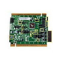
... Figure 1: TWR-S08MM128 Module TWR-S08MM128-KIT Freescale Tower System The TWR-S08MM128 module is part of the Freescale Tower System, a modular development platform that enables rapid prototyping and tool re-use through reconfigurable hardware. Take your design to the next level and begin constructing your Tower System today. ...
Page 3
... ADC)—all in one cost-effective, 8-bit microcontroller. S08MM devices are ideal for portable medical applications or any other application requiring a significant amount of precision analog such as instrumentation and industrial control. The TWR-S08MM128-KIT features the 8-bit MC9S08MM128 and consists of the following components: • TWR-S08MM128—Also referred to as ...
Page 4
... TOWER SYSTEM Primary edge of TWR-S08MM128 and TWR-SER must connect to this Primary elevator, which has components on the bottom of the board, including the mini- USB connector. Figure 2: Tower System Assembled NOTE: Figure Tower System without the optional MED-EKG assembly. For details on how to assemble the MED-EKG, please refer to Lab 1 on the DVD. ...
Page 5
... Quick Start Guide for TWR-S08MM128-KIT Step-by-Step Installation Instructions In this Quick Start Guide, you will learn how to set up the TWR-S08MM128-KIT. STEP Install Software 1 and Tools • Install CodeWarrior Development Studio for Microcontrollers V6.3 (Evaluation Version) • Processor Expert V3.09 (graphical code generator) • Install Service Pack for S08MM • Install Flexis MM USB Bootloader GUI (Required for Lab 5) • Install Freescale USB stack with PHDC v2 ...
Page 6
... J26 2 and 3 J25 6 and 5, nothing on pin J24 Open J11 1 and and and 2 J18 1 and 2, 3 and 4, 5 and 6, 7 and 8, 9 and 10, 11 and 12, 13 and 14 SW3 Slider 1 at OFF (Position 1) Slider 2 at OFF (Position 2) Table 1: Default Settings on TWR-S08MM128 Module ...
Page 7
... STEP (continued from previous page his step is only needed for the Lab 1 EKG demo. V erify the MED-EKG module is configured to default settings. This is required to run the MED-EKG demo. Figure 4: MED-EKG with Default Jumpers Used in Table 2 NOTE: Please see MED-EKG schematic for jumper labels and functions. Jumper Default Setting on TWR-S08MM128 Module Name J2 1 and and and 3 J5 Open J6 2 and 3 J7 ...
Page 8
... Be sure to connect TWR-SER USB before the TWR-S08MM128 USB. Do not connect TWR-S08MM128 USB without TWR-SER USB or damage could result. NOTE: When the TWR-S08MM128 module is used stand-alone, USB port (J17) is both the power source and the debugger interface. When the TWR-S08MM128 module is assembled as a Tower System, the USB port (J17) is only a OSBDM. LEDs correspond to silk-screened labels D9 to D12 on the TWR-S08MM128 module. ...
Page 9
... Quick Start Guide for TWR-S08MM128-KIT STEP Program S08MM128 4 and Debug Code 1. To program the S08MM128 with a different application, connect the USB from the PC to the TWR-SER, and then connect another USB from the PC to TWR-S08MM128. If this is the first time you have connected the board, a window may appear and ask about installing new hardware for the on-board OSBDM circuit ...
Page 10
... S08MM128 internal flash the True-Time Simulator and Real-Time Debugger window, click (start and continue) to run the application. Rotate the potentiometer back and forth from the TWR-S08MM128 module. You will see that LED 1 to LED 4 will turn off and on sequentially depending upon the rotation of the potentiometer the same debugger window, you can click on this button to halt the application ...
Page 11
... Quick Start Guide for TWR-S08MM128-KIT STEP Demonstrate 5 the Labs • Lab 1: MED-EKG Development Board Demo—Set up hardware and run software to read your electrocardiography • Lab 2: Interfacing with HealthLink and Google Health—Send emulated health data to HealthLink and Google Health • Lab 3: Low-Power and Measurement Engine Demo—Explore the energy ...
Page 12
... For further information, visit freescale.com or contact your Freescale sales representative. For information on Freescale’s Environmental Products program, visit freescale.com/epp. To learn more about the TWR-S08MM128-KIT and other Freescale medical products, please visit freescale.com/s08mm, freescale.com/medical and freescale.com/tower. Freescale, the Freescale logo and CodeWarrior are trademarks of Freescale Semiconductor, Inc., Reg. U.S. Pat. & ...