AD8312ACBZ-P7 Analog Devices Inc, AD8312ACBZ-P7 Datasheet - Page 18
AD8312ACBZ-P7
Manufacturer Part Number
AD8312ACBZ-P7
Description
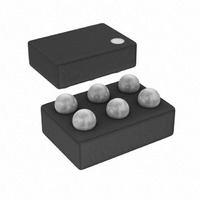
IC DETECTOR RF LOGIC 6-WLCSP
Manufacturer
Analog Devices Inc
Type
Logarithmic Amplifierr
Datasheet
1.AD8312ACBZ-P7.pdf
(20 pages)
Specifications of AD8312ACBZ-P7
Rf Type
Cellular, GSM, CDMA, W-CDMA
Frequency
50MHz ~ 3.5GHz
Input Range
-45dBm ~ 0dBm
Accuracy
±1dB
Voltage - Supply
2.7 V ~ 5.5 V
Current - Supply
5.7mA
Package / Case
6-UFBGA, 6-uCSP
Frequency Range
50MHz To 3.5GHz
Power Range
-45dBm To 0dBm
Sensitivity
0.0073dB/°C
Supply Current
4.2mA
Supply Voltage Range
2.7V To 5.5V
Rf Ic Case Style
WLCSP
Number Of Channels
1
Number Of Elements
1
Power Supply Requirement
Single
Input Resistance
0.013MOhm
Input Bias Current
75uA
Single Supply Voltage (typ)
3V
Dual Supply Voltage (typ)
Not RequiredV
Power Dissipation
200mW
Rail/rail I/o Type
No
Single Supply Voltage (min)
2.7V
Single Supply Voltage (max)
5.5V
Dual Supply Voltage (min)
Not RequiredV
Dual Supply Voltage (max)
Not RequiredV
Operating Temp Range
-40C to 85C
Operating Temperature Classification
Industrial
Mounting
Surface Mount
Pin Count
6
Package Type
WLCSP
Lead Free Status / RoHS Status
Lead free / RoHS Compliant
Lead Free Status / RoHS Status
Lead free / RoHS Compliant, Lead free / RoHS Compliant
Other names
AD8312ACBZ-P7
AD8312ACBZ-P7TR
AD8312ACBZ-P7TR
Available stocks
Company
Part Number
Manufacturer
Quantity
Price
Company:

Part Number:
AD8312ACBZ-P7
Manufacturer:
ADI
Quantity:
9 000
Company:
Part Number:
AD8312ACBZ-P7
Manufacturer:
ST
Quantity:
320


AD8312
Table 6. Evaluation Board Configuration Options
Component
VPOS, GND
C2
R1
R2, R4
C3
R3, R8, C4
R7
R5, R6
Function
Supply and Ground Vector Pins.
Power Supply Decoupling. The nominal supply decoupling consists of a 0.1 μF capacitor (C1).
Input Interface. The 52.3 Ω resistor in Position R1 combines with the AD8312’s internal input impedance
to give a broadband input impedance of around 50 Ω.
Slope Adjust. By installing resistors in R2 and R4, the nominal slope of 20 mV/dB can be changed. See the
Increasing the Logarithmic Slope section for more details.
Filter Capacitor. The response time of VOUT can be modified by placing a capacitor between CFLT (Pin 4)
and VOUT (Pin 2).
Output Interface. R3, R8, and C4 can be used to check the response of VOUT to capacitive and resistive
loading. R3/R8 can be used to attenuate VOUT.
VSET Interface. R7 can be used to reduce capacitive loading from transmission lines.
Alternate Interface. R5 and R6 allow for VOUT and VSET to be accessible from the edge connector, which
is only used for characterization.
Rev. A | Page 18 of 20
Default
Condition
Not Applicable
C2 = 0.1 μF
(Size 0603)
R1 = 52.3 Ω
(Size 0603)
R2 = Open
(Size 0402)
R4 = 0 Ω
(Size 0402)
C3 = Open
(Size 0603)
R3 = 0 Ω
(Size 0603)
R8 = C4 = Open
(Size 0402)
R7 = 0 Ω
(Size 0603)
R5 = R6 = Open
(Size 0402)
Related parts for AD8312ACBZ-P7
Image
Part Number
Description
Manufacturer
Datasheet
Request
R

Part Number:
Description:
High-Performance, Low Distortion 500-MHz Mixer
Manufacturer:
Analog Devices
Datasheet:

Part Number:
Description:
MIXER IC
Manufacturer:
Analog Devices Inc
Datasheet:
Part Number:
Description:
MIXER IC
Manufacturer:
Analog Devices Inc
Datasheet:

Part Number:
Description:
±1.7g Dual-Axis IMEMS Accelerometer Evaluation Board
Manufacturer:
Analog Devices Inc
Datasheet:

Part Number:
Description:
Inertial Sensor Evaluation System
Manufacturer:
Analog Devices Inc
Datasheet:
Part Number:
Description:
Manufacturer:
Analog Devices Inc
Datasheet:
Part Number:
Description:
Manufacturer:
Analog Devices Inc
Datasheet:
Part Number:
Description:
Manufacturer:
Analog Devices Inc
Datasheet:
Part Number:
Description:
Manufacturer:
Analog Devices Inc
Datasheet:
Part Number:
Description:
Manufacturer:
Analog Devices Inc
Datasheet:
Part Number:
Description:
Manufacturer:
Analog Devices Inc
Datasheet:
Part Number:
Description:
Manufacturer:
Analog Devices Inc
Datasheet: