20-101-1207 Rabbit Semiconductor, 20-101-1207 Datasheet
20-101-1207
Specifications of 20-101-1207


Related parts for 20-101-1207


20-101-1207 Summary of contents
Page 1
... RabbitCore RCM4500W C-Programmable ZigBee Core Module User’s Manual 019–0161 • 090515–G ...
Page 2
... RabbitCore RCM4500W User’s Manual Part Number 019-0161 • 090515–G • Printed in U.S.A. ©2007–2009 Digi International Inc. • All rights reserved. No part of the contents of this manual may be reproduced or transmitted in any form or by any means without the express written permission of Digi International. ...
Page 3
... Online Documentation ..................................................................................................................7 Chapter 2. Getting Started 2.1 Install Dynamic C .................................................................................................................................9 2.2 Hardware Connections........................................................................................................................10 2.2.1 Step 1 — Prepare the Prototyping Board for Development........................................................10 2.2.2 Step 2 — Attach Module to Prototyping Board..........................................................................11 2.2.3 Step 3 — Connect Programming Cable ......................................................................................12 2.2.4 Step 4 — Connect Power ............................................................................................................13 2.3 Run a Sample Program .......................................................................................................................14 2 ...
Page 4
Other Hardware .................................................................................................................................. 42 4.5.1 Clock Doubler ............................................................................................................................ 42 4.5.2 Spectrum Spreader...................................................................................................................... 42 4.6 Memory .............................................................................................................................................. 43 4.6.1 SRAM......................................................................................................................................... 43 4.6.2 Flash EPROM............................................................................................................................. 43 Chapter 5. Software Reference 5.1 More About Dynamic C ..................................................................................................................... 45 5.2 Dynamic C Function ...
Page 5
... D.1.2 Dynamic C v. 10.21 (RCM4510W preview and standard versions)........................................102 D.1.3 Dynamic C v. 10.11 (RCM4510W preview version only) ......................................................103 D.2 Digi ® XBee USB Configuration .....................................................................................................104 D.2.1 Additional Reference Information ...........................................................................................106 D.2.2 Update Digi ® XBee USB Firmware........................................................................................106 Index Schematics User’s Manual 97 101 107 111 ...
Page 6
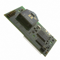
RabbitCore RCM4500W ...
Page 7
... Rabbit 4000’s internal real-time clock and the static RAM. One 50-pin header brings out the Rabbit 4000 I/O bus lines, parallel ports, and serial ports. A separate 14-pin auxiliary I/O header brings out up to nine additional I/O pins (up to four of which may be configured as analog inputs) made possible by the onboard XBee RF module ...
Page 8
... SDLC/HDLC serial ports; 1 asynchronous serial port is shared with the XBee RF module 1 asynchronous serial port is used during programming Digi International ® XBee ® ZB (802.15.4 standard, ISM 2.4 GHz) RCM4510W (ZNet) (20-101-1207) RCM4510W (ZB) (20-101-1269) RabbitCore RCM4500W ...
Page 9
... RF module is made of discrete onboard components in the preview version, and is included in the pluggable Digi International on the standard release. The height of the preview version is also about 0.01” (0.2 mm) less than that of the standard release; Rabbit recommends that you use the dimensions for the standard release specified in this manual in your design ...
Page 10
... Rabbit Field Utility to download compiled Dynamic C .bin files, and cloning board options for rapid production loading of programs. • Generous memory size allows large programs with tens of thousands of lines of code, and substantial data storage. • Reference application uses a low-cost, low-power ZigBee/802.15.4 infrastructure to connect Rabbit-based devices • ...
Page 11
... XBee USB (used as ZigBee coordinator). ® • Dynamic C CD-ROM, with complete product documentation on disk. • Getting Started instructions. • A bag of accessory parts for use on the Prototyping Board. • Rabbit 4000 Processor Easy Reference poster. • Registration card. RabbitCore RCM4510W ® The RCM4510W RabbitCore module features built-in ZigBee /802 ...
Page 12
... XBee RF module identifies the factory-installed firmware type. Older RCM4510W modules shipped with ZNet firmware and do not have a sticker on their XBee RF module. • ZNet 2 networking solution that was developed around an earlier draft of the Zig- Bee standard, and will work only with the MaxStream or Digi International modules used with the RCM4510W or with the preview version of the RCM4510W ...
Page 13
... Online Documentation The online documentation is installed along with Dynamic C, and an icon for the docu- mentation menu is placed on the workstation’s desktop. Double-click this icon to reach the menu. If the icon is missing, use your browser to find and load folder, found in the Dynamic C installation folder. ...
Page 14
RabbitCore RCM4500W ...
Page 15
... The installation allows you to choose the COM port that will be used. The default selec- tion is COM1. You may select any available port for Dynamic C’s use. If you are not cer- tain which port is available, select COM1. This selection can be changed later within Dynamic C ...
Page 16
... Connect the programming cable between the RCM4510W and the PC. 4. Connect the power supply to the Prototyping Board. 2.2.1 Step 1 — Prepare the Prototyping Board for Development Snap in four of the plastic standoffs supplied in the bag of accessory parts from the Devel- opment Kit in the holes at the corners on the bottom side of the Prototyping Board as shown in Figure 3 ...
Page 17
... Prototyping Board with the programming header at the top right. Insert the metal standoffs as shown in Figure 4, secure them from the bottom using the 4-40 screws and washers, then insert the module’s header J1 on the bottom side into socket RCM1 on the Prototyping Board. ...
Page 18
... Your PC should recognize the new USB hardware, and the LEDs in the shrink-wrapped area of the USB programming cable will flash — if you get an error message, you will have to install USB drivers. Drivers for Windows XP are available in the Dynamic C Drivers\Rabbit USB Programming Cable\WinXP_2K to install the USB drivers ...
Page 19
... Release the clip to secure the plug assembly in the AC adapter. Connect the AC adapter to 3-pin header J1 on the Prototyping Board as shown in Figure 5. The connector may be attached either way as long not offset to one side—the center pin always connected to the positive terminal, and either edge pin is ground. ...
Page 20
... Dynamic C icon on your desktop or in your You may have to select the COM port assigned to the USB programming cable on your PC. In Dynamic C, select Options > Project Options “Communications” tab. Then check “Use USB to Serial Converter” in “Serial Options.” Click to save the settings. OK ...
Page 21
... Appendix D provides additional configuration information if you experience conflicts while doing development simultaneously with more than one ZigBee coordinator you wish to install new firmware. Different firmware must be installed to use the RCM4510W as either a coordinator end device. User’s Manual ® XBee USB is used as the ZigBee coordinator. , which is in the Dynamic C ...
Page 22
... RCM4510W series of modules and the Prototyping Board. For advanced development topics, refer to the Dynamic C User’s Manual, also in the online documentation set. An Introduction to ZigBee provides background information on the ZigBee protocol, and is available on the CD and on our 2 ...
Page 23
... ZigBee features. NOTE: The sample programs assume that you have at least an elementary grasp of the C language. If you do not, see the introductory pages of the Dynamic C User’s Manual for a suggested reading list. In order to run the sample programs discussed in this chapter and elsewhere in this manual, 1. Your module must be plugged in to the Prototyping Board as described in Chapter 2, “ ...
Page 24
... Dynamic C STDIO window. Press “2” or “3” on your keyboard to select LED DS2 or DS3 on the Prototyping Board. Then follow the prompt in the Dynamic C or OFF. A logic low will light up the LED you selected. —demonstrates the use of assembly language to flash LEDs DS2 and • ...
Page 25
... TAMPERDETECTION.C mode. When an attempt is detected, the battery-backed onchip-encryption RAM on the Rabbit 4000 is erased. This battery-backed onchip-encryption RAM can be useful to store data such as an AES encryption key from a remote location. This sample program shows how to load and read the battery-backed onchip-encryption RAM and how to enable a visual indicator ...
Page 26
... Serial Port D for • FLOWCONTROL.C CTS/RTS flow control with serial data coming from Serial Port C (TxC) at 115,200 bps. The serial data received are displayed in the To set up the Prototyping Board, you will need to tie TxD and RxD ...
Page 27
... Since the J4 header locations on the two Prototyping Boards are connected with wires, there are no slip-on jumpers either Prototyping Board. —This program demonstrates transmitting and then receiving an • SWITCHCHAR.C ASCII string on Serial Ports C and D. It also displays the serial data received from both ports in the window ...
Page 28
... IDC header supplied with the accessory parts in the Development Kit. Once you have compiled and run this program, press and release switches the Prototyping Board. The data echoed between the serial ports will be displayed in the 22 —This program demonstrates how to set up Serial Ports E IOCONFIG.EXE library generated by window. STDIO window. ...
Page 29
... SAMPLES\RTCLOCK program in the Dynamic C SAMPLES\RTCLOCK how to read and set the real-time clock. 3.2.3 ZigBee Sample Programs Section 6.2 describes the sample programs associated with the XBee RF module. User’s Manual sample program from the Dynamic C RTC_TEST.C folder provides additional examples of sample 23 ...
Page 30
RabbitCore RCM4500W ...
Page 31
... Chapter 4 describes the hardware components and principal hardware subsystems of the RCM4510W. Appendix A, “RCM4510W Specifica- tions,” provides complete physical and electrical specifications. Figure 6 shows the Rabbit-based subsystems designed into the RCM4510W. Figure 6. RCM4510W Subsystems User’s Manual 4. H ARDWARE R EFERENCE 25 ...
Page 32
RCM4510W Digital Inputs and Outputs Figure 7 shows the RCM4510W pinouts for headers J1 and J4. standard 2 × 25 IDC header with a nominal 1.27 mm pitch, and header J4 is Headers standard 2 ...
Page 33
... Figure 8 shows the use of the Rabbit 4000 microprocessor ports in the RCM4510W modules. Figure 8. Use of Rabbit 4000 Ports The ports on the Rabbit 4000 microprocessor used in the RCM4510W are configurable, and so the factory defaults can be reconfigured. Table 2 lists the Rabbit 4000 factory defaults and the alternate configurations. User’s Manual 27 ...
Page 34
... PB6 Input/Output 23 PB7 Input/Output 28 Default Use Alternate Use Reset input Slave port data bus (SD0–SD7) External I/O data bus (ID0–ID7) SCLK External I/O Address IA6 SCLKA External I/O Address IA7 /SWR External I/O Address IA0 /SRD External I/O Address ...
Page 35
... Input/Output 27 PC3 Input/Output 28 PC4 Input/Output 29 PC5 Input/Output 30 PC6 Input/Output 31 PC7 Input/Output 32 PE0 Input/Output User’s Manual Default Use Alternate Use TXD I/O Strobe I0 Timer C0 TCLKF RXD/TXD I/O Strobe I1 Timer C1 RCLKF Input Capture TXC/TXF I/O Strobe I2 Timer C2 RXC/TXC/RXF I/O Strobe I3 Timer C3 SCLKD ...
Page 36
Table 2. RCM4510W Pinout Configurations (continued) Pin Pin Name 33 PE1 Input/Output 34 PE2 Input/Output 35 PE3 Input/Output 36 PE4 Input/Output 37 PE5/SMODE0 Input/Output 38 PE6/SMODE1 Input/Output 39 PE7/STATUS Input/Output 30 Default Use Alternate Use I/O Strobe I1 A21 Timer ...
Page 37
... Pin Name 40 PD0 Input/Output 41 PD1 Input/Output 42 PD2 Input/Output 43 PD3 Input/Output 44 PD4 Input/Output 45 PD5 Input/Output User’s Manual Default Use Alternate Use I/O Strobe I0 Timer C0 D8 INT0 SCLKD/TCLKF QRD1B IA6 I/O Strobe I1 Timer C1 D9 INT1 RXD/RCLKF QRD1A Input Capture I/O Strobe I2 Timer C2 ...
Page 38
... Analog Input Analog Input Analog reference voltage (1.2 V) Notes Serial Port E (RCM4510W only) Reserved for future use Ground Software-selectable Software-selectable Software-selectable Software-selectable Software-selectable, analog ref. voltage not presently supported Used by XBee RF module to place or remove remaining RCM4510W circuitry in “sleep” mode RabbitCore RCM4500W ...
Page 39
... Parallel Port A can also be used as an external I/O data bus to isolate external I/O from the main data bus. Parallel Port B pins PB2–PB7 can also be used as an auxiliary address bus. When using the external I/O bus for any reason, you must add the following line at the beginning of your program ...
Page 40
... RCM4510W is operating in the Run Mode. Serial Port B is shared with the RCM4510W module’s asynchronous XBee RF module. Flow control for the XBee RF module is provided from the Rabbit 4000 RxD+ and TxD– Ethernet pins. Serial Ports C and D can also be operated in the clocked serial mode. In this mode, a clock line synchronously clocks the data in or out ...
Page 41
... NOCHARASSYINBRK #define RS232_NOCHARASSYINBRK This macro is already defined so that it is the default behavior for the sample programs in the Dynamic C SAMPLES\RCM4500W\SERIAL User’s Manual Serial Port E Serial Port F RCLKE and RCLKF must be selected the same parallel port as TXE and TXF respectively. library requires you to define the macro folder ...
Page 42
... Alternate Uses of the Programming Port All three Serial Port A signals are available as • a synchronous serial port • an asynchronous serial port, with the clock line usable as a general CMOS I/O pin The programming port may also be used as a serial port via the programming cable. ...
Page 43
... Run Mode when no programming cable is attached. When the Rabbit 4000 is reset, the operating mode is determined by the status of the SMODE pins. When the programming cable’s the SMODE pins are pulled high, placing the Rabbit 4000 in the Program Mode. When the programming cable’ ...
Page 44
... A program “runs” in either mode, but can only be downloaded and debugged when the RCM4510W is in the Program Mode. Refer to the Rabbit 4000 Microprocessor User’s Manual gramming port. 4.3.2 Standalone Operation of the RCM4510W Once the RCM4510W has been programmed successfully, remove the programming cable from the programming connector and reset the RCM4510W ...
Page 45
... All the pins have the following software-configurable features. • Selectable as input or output. • Output is either sinking or sourcing, and may be set up for a default high or low. • Can be pulled up internally. The four digital I/O, DIO0–DIO3, are similar to the general-purpose I/O, but may instead by configured in software as analog inputs ...
Page 46
... Figure 10. Resistor Divider Network for Analog Inputs The R1 resistors are typically 20 kΩ to 100 kΩ, with a lower resistance leading to more accuracy, but at the expense of a higher current draw. The R0 resistors would then be 180 kΩ to 900 kΩ for a 10:1 attenuator. The capacitor filters noise pulses on the A/D converter input ...
Page 47
... Other Pin Features There are two other features brought out on the auxiliary I/O header J4. • There is a +3.3 V power supply point on pin 8, which can deliver 3.3 V DC. This power supply point is essentially a filtered and isolated version of the regu- lated +3 power that is supplied to the RCM4510W RabbitCore module through pin 1 of header J1 from the motherboard. • ...
Page 48
... The spectrum spreader will be set according to the macro OK value whenever a program is compiled using this project file. NOTE: Refer to the Rabbit 4000 Microprocessor User’s Manual for more information on the spectrum-spreading setting and the maximum clock speed. 42 Options > Project Options RabbitCore RCM4500W menu ...
Page 49
... EPROM since it may be necessary to change the sector size in the future. Writing to arbitrary flash memory addresses at run time is discouraged. Instead, define a “user block” area to store persistent data. The functions writeUserBlock and readUserBlock are provided for this. Refer to the for additional information. ...
Page 50
RabbitCore RCM4500W ...
Page 51
... Dynamic C development environment. Debugging occurs while the application runs on the target. Alternatively, users can compile a program to an image file for later loading. Dynamic C runs on PCs under Windows NT and later— see Rabbit’s Technical Note TN257, Running Dynamic C additional information if you are using a Dynamic C under Windows Vista ...
Page 52
... C, SPI, GPS, file system. LCD display and keypad drivers. • Powerful language extensions for cooperative or preemptive multitasking • Loader utility program to load binary images into Rabbit targets in the absence of Dynamic C. • Provision for customers to create their own source code libraries and augment on-line help by creating “ ...
Page 53
... Certain function calls involve reading and storing calibration constants from/to the simulated EEPROM in flash memory located at the top 2K of the reserved user block memory area (3800–39FF). This leaves the address range 0–37FF in the user block available for your application. These address ranges may change in the future in response to the volatility in the flash memory market, in particular sector size ...
Page 54
... BIOSLIB\CLONECONFIG.LIB RCM4510W master will not run the application, and further debugging is not possible as long as the CL_FORCE_MASTER_MODE modules will be “sterile,” meaning that they cannot be used as a master for cloning. To develop and debug an application on an RCM4510W, comment out the macro or set MASTER_MODE NOTE: Instead of defining this macro is your application, you may simply add the line CL_FORCE_MASTER_MODE=1 under the Dynamic C Options > ...
Page 55
... RCM4510W clone will reset or boot up normally. 5.2.6 ZigBee Drivers The ZigBee drivers are located in the tion on these libraries and the ZigBee function calls is provided in Section 6.4. User’s Manual — error returns, the firmware update will folder. Complete informa- LIB\Rabbit4000\XBee 49 ...
Page 56
Prototyping Board Function Calls The function calls described in this section are for use with the Prototyping Board features. The source code is in the Dynamic C library if you need to modify it for your own board design. ...
Page 57
... PARAMETERS the input port data register to poll (e.g., PADR) dataport the input port bit (0–7) to poll portbit the value receive value the duration of the timeout in seconds (enter 0 for no timeout) ...
Page 58
Auxiliary I/O Pins Function Calls The function calls described in this section are for use with the pins on the auxiliary I/O header at J4. The source code is in the Dynamic C library if you need to modify ...
Page 59
... DIO_05 XBEE_IO_CONF_DIGOUT_HIGH // bit 8 #define DIO_04 XBEE_IO_CONF_DIGOUT_HIGH // bit 0 #define DIO_10 XBEE_IO_CONF_DIGOUT_LOW #define DIO_11 XBEE_IO_CONF_DIGIN NOTE: The mask order is different than for DIO_INPUTS. While all pins can be config- ured as either inputs or outputs, only DIO_00 – DIO_03 can be configured as analog inputs. RETURN VALUE 0 — success. ≠ ...
Page 60
... Reads the logic state of a pin configured as a digital input pin. This value corresponds to the dio number. PARAMETERS the Dynamic C digital input pin number (0 – ZB_MAX_PIN, valid dio values are 0–5, 10–12) set up in zb_io_init(). NOTE: The pin number is not the same as the DIO_xx macros described in zb_io_ init(), which are used to configure the function of the pin only ...
Page 61
... Reads the analog input on the designated pin and return its 10-bit value. To convert the reading to millivolts perform the following calculation. AD (mV) = (ADIO reading / 1023) × 1200 mV PARAMETER the Dynamic C analog input pin number (0–3) set up in zb_io_ dio init(). NOTE: The pin number is not the same as the DIO_xx macros described in zb_io_ init(), which are used to configure the function of the pin only ...
Page 62
Upgrading Dynamic C Dynamic C patches that focus on bug fixes are available from time to time. Check the Web site www.rabbit.com/support/ 5.3.1 Add-On Modules Starting with Dynamic C version 10.40, Dynamic C includes the popular µC/OS-II real- time ...
Page 63
... As a router. Routers pass data from other devices. • end device. End devices contain just enough functionality to talk to their parent node (either the coordinator or a router), and cannot relay data from other devices. The XBee RF module used by the RCM4510W (ZB) sup- ports using the RCM4510W RabbitCore module in a mesh network ...
Page 64
... Table 1). Older RCM4510W modules shipped with ZNet firmware and do not have a sticker on their XBee RF module. • ZNet 2.5 firmware is supported by Dynamic C v. 10.21 and later versions. (Preview versions of the RCM4510W will work with Dynamic C v. 10.11 and later.) • ...
Page 65
... XBee USB used as the ZigBee coordinator must be connected to an avail- able USB port on your PC if you are exercising the ZigBee protocol, or you need a second RCM4510W module if so instructed. Refer to Chapter 2, “Getting Started,” if you need further information on these steps. To run a sample program, open it with the and run it by pressing ...
Page 66
... Control Panel > System > Hardware > Device Manager > Ports PC if you need help in identifying the USB COM port. 5. Any ZigBee devices discovered will be displayed in the “Devices Discovered” window to the right. If the utility times out and no ZigBee devices are displayed, you will have to reconfig- ure the Digi ® ...
Page 67
... Change the extended PAN ID if you are developing simultaneously with more than one ZigBee coordinator. #define DEFAULT_EXTPANID "0x0123456789abcdef" Channel mask — defaults to 0x1FFE, i.e., all 12 possible channels via the macro in the Dynamic C LIB\Rabbit4000\XBee\XBEE_API.LIB 15 for campatibility with the XBee PRO.) #define DEFAULT_CHANNELS XBEE_DEFAULT_CHANNELS User’ ...
Page 68
... You may type in either “ATxx” or just the “xx” part of the command. • Use just the AT command to read any of the values. • Use [AT]xx yyyy (where the integer bits) to set any of the “set or read” values. (Note that this works for NI, the node identifier, where the data will be a Node ID.string in quotes — ...
Page 69
... Plug the AC adapter back in to apply power to the Prototyping Board once again. Once the XBee RF module on the RCM4510W completes its initialization (it joins the network), you will be prompted to enter a “sleep” time in milliseconds — enter the number followed by the Enter RCM4510W module powers off ...
Page 70
... RAM before the RCM4510W module is placed in the sleep mode. —This sample program shows how to set up and use endpoints • XBEE_GPIO_SERVER.C and clusters meant to be run with the Windows GUI client (installed in Dynamic C’s directory) and a Digi USB XBee coordinator or with the GPIO client Utilities sample program ( SAMPLES/XBEE/XBEE_GPIO_CLIENT.C RabbitCore module single-board computer with a separate XBee RF module ...
Page 71
... While SP is measured in 0.01 second intervals, it only has a 0.25 second resolution, and any value sent to the XBee RF module is rounded automatically. - The overhead of polling for a message was tested internally and was found to be approximately 20 ms. Thus a hypothetical sleep with SN = 100 and SP = 100 will not wake the Rabbit microproces- sor until 102 seconds have elapsed (rather than the expected 100 seconds) ...
Page 72
... RCM4510W to receive. Like ST, this parameter must be set carefully to ensure no mes- sages are lost at startup currently set to 3 seconds. • conditional flag and determines whether the XBee RF module will wake the Rabbit 4000 microprocessor if SN and SP expire, or whether both parameters are reset to resume the sleep mode immediately ...
Page 73
... If there are any problems at this point: • Use the Dynamic C Help • Check the Rabbit Technical Bulletin Board and forums at and at www.rabbitcom/forums/. • Use the Technical Support e-mail form at www.rabbit.com/support/. If the sample programs ran fine, you are now ready to go on. ...
Page 74
RabbitCore RCM4500W ...
Page 75
... Appendix A provides the specifications for the RCM4510W, and describes the conformal coating. User’s Manual A A. RCM4510W PPENDIX S PECIFICATIONS 69 ...
Page 76
A.1 Electrical and Mechanical Characteristics Figure A-1 shows the mechanical dimensions for the RCM4510W. Figure A-1. RCM4510W Dimensions NOTE: All measurements are in inches followed by millimeters enclosed in parentheses. All dimensions have a manufacturing tolerance of ±0.01" (0.25 mm). ...
Page 77
... It is recommended that you allow for an “exclusion zone” of 0.04" (1 mm) around the RCM4510W in all directions when the RCM4510W is incorporated into an assembly that includes other printed circuit boards. An “exclusion zone” of 0.08" (2 mm) is recom- mended below the RCM4510W when the RCM4510W is plugged into another assembly. ...
Page 78
... Connection for user-supplied backup battery (to support RTC and data SRAM parallel digital I/0 lines: • Rabbit 4000 pins configurable with four layers of alternate functions • XBee RF module pins, four of which may be * configured as analog inputs Startup mode (2), reset in Status, reset out 4 channels single-ended 0– ...
Page 79
... V.DC ±5% 150 mA @ 3.3 V while transmitting/receiving 3.3 V while not transmitting/receiving <20 µA @ 3.3 V while asleep -40°C to +85° 95%, noncondensing One 2 × pitch IDC signal header One 2 × 25, 1.27 mm pitch IDC signal header One 2 × ...
Page 80
... Digi International XBee 802.15.4 standard (ZigBee compliant) ISM 2.4 GHz 100 ft (30 m) 300 ft ( dBm) 250,000 bps -92 dBm (1% PER) Chip antenna • Point-to-point • Point-to-multipoint • Peer-to-peer • Mesh 16 direct-sequence channels • PAN ID • Channel • Source/destination addresses 3 ± 3 ±5% RabbitCore RCM4500W ...
Page 81
... SMT header with pin spacing Figure A-3 shows the layout of another board for the RCM4510W to be plugged into. These reference design values are relative to one of the mounting holes. Figure A-3. User Board Footprint for RCM4510W User’s Manual 75 ...
Page 82
... V, 25°C All other I/O I DRIVE (except TXD+, TXDD+, TXD-, TXDD-) 76 Parameter Maximum Rating -40° to +85°C -55° to +125°C VDD IO (max. 3 –40°C to +85°C, VDD A Min 3 Typ Max 3.3 V 3.6 V 1.8 V 1.90 V 2.0 V ...
Page 83
... Be sure to add the loads for the devices you are using in your custom system and verify that they do not exceed the values in Table A-6. Table A-6. External Capacitive Bus Loading -40°C to +85°C Output Port All I/O lines with clock doubler enabled User’s Manual Input Output Capacitance Capacitance (pF) ...
Page 84
... Figure A-4 shows a typical timing diagram for the Rabbit 4000 microprocessor external I/O read and write cycles. Figure A-4. External I/O Read and Write Cycles—No Extra Wait States NOTE: /IOCSx can be programmed to be active low (default) or active high. 78 RabbitCore RCM4500W ...
Page 85
... The measurements are taken at the 50% points under the following conditions. • -40°C to 85° VDD • Internal clock to nonloaded CLK pin delay ≤ 85°C/3.0 V The clock to address output delays are similar, and apply to the following delays. • the clock to address delay adr • ...
Page 86
... Any components in the conformally coated area may be replaced using standard soldering procedures for surface-mounted components. A new conformal coating should then be applied to offer continuing protection against the effects of moisture and contaminants. NOTE: For more information on conformal coatings, refer to Rabbit’s Technical Note TN303, Conformal Coatings, which is included with the online documentation. 80 ...
Page 87
... JP2 on J1 pin 38 PE7 or STATUS Output JP3 on J1 pin 39 JP4 LN0 or PD0 on J1 pin 40 User’s Manual Pins Connected 1–2 PE5 2–3 SMODE0 1–2 PE6 2–3 SMODE1 1–2 PE7 2–3 STATUS 1–2 LN0 2–3 PD0 Factory Default × × × × 81 ...
Page 88
... NOTE: The jumper connections are made using 0 Ω surface-mounted resistors. 82 Pins Connected 1–2 LN2 2–3 PD2 1–2 LN4 2–3 PD4 1–2 LN6 2–3 PD6 1–2 LN7 2–3 PD7 1–2 LN5 2–3 PD5 1–2 LN3 2–3 PD3 1–2 LN1 2–3 PD1 RabbitCore RCM4500W Factory Default × × × × ...
Page 89
... RCM4510W and to build prototypes of your own circuits. The Prototyping Board has power-supply connec- tions and also provides some basic I/O peripherals (RS-232, LEDs, and switches), as well as a prototyping area for more advanced hardware development. User’s Manual B. P ROTOTYPING B OARD ...
Page 90
B.1 Introduction The Prototyping Board included in the Development Kit makes it easy to connect an RCM4510W module to a power supply and a PC workstation for development. It also pro- vides some basic I/O peripherals (RS-232, LEDs, and switches), ...
Page 91
... The header plug leading to bare leads provided for overseas customers can be connected to the 3-pin header in either orientation. Users providing their own power supply should ensure that it delivers 8– The voltage regulators will get warm while in use. Regulated Power Supply • ...
Page 92
... NOTE: No analog signals are available on the Prototyping Board with the RCM4510W RabbitCore module installed since no analog signals are present on the RCM4510W’s header J1. The auxiliary I/O on the RCM4510W’s header J4 cannot be used with the Prototyping Board without modifying the Prototyping Board. ...
Page 93
... B.2 Mechanical Dimensions and Layout Figure B-2 shows the mechanical dimensions and layout for the Prototyping Board. Figure B-2. Prototyping Board Dimensions NOTE: All measurements are in inches followed by millimeters enclosed in parentheses. All dimensions have a manufacturing tolerance of ±0.01" (0.25 mm). User’s Manual 87 ...
Page 94
... Prototyping Area Connectors B.3 Power Supply The RCM4510W requires a regulated 3.0 V – 3 power source to operate. Depend- ing on the amount of current required by the application, different regulators can be used to supply this voltage. The Prototyping Board has an onboard +5 V switching power regulator from which a +3 ...
Page 95
... Figure B-4. Prototyping Board Pinout Although analog signals are shown for labeled points at header location J3 on the Prototyping Board, the analog signals on the RCM4510W are associated with the XBee RF module. These analog signals are not brought out to the Prototyping Board. User’s Manual 89 ...
Page 96
... The holes in the prototyping area are spaced at 0.1" (2.5 mm). +3 and GND traces run along the top edge of the prototyping area for easy access. Small to medium circuits can be prototyped using point-to-point wiring with AWG wire between the proto- typing area, the +3 and GND traces, and the surrounding area where surface- mount components may be installed ...
Page 97
... Figure B-5. Prototyping Board Current-Measurement Option NOTE: Once you have cut the trace below header location JP1 or JP2, you must either be using the ammeter or have a jumper in place in order for power to be delivered to the Prototyping Board. User’s Manual 91 ...
Page 98
... A/D converter chip, which is available on other RabbitCore modules based on the Rabbit 4000 microprocessor, but is not installed on the RCM4510W model. the auxiliary I/O on the RCM4510W’s header J4 cannot be used with the Prototyping Board with- out modifying the Prototyping Board. B.4.4 Serial Communication The Prototyping Board allows you to access the serial ports from the RCM4510W mod- ule ...
Page 99
... RS232.LIB of the flow control lines are specified using a set of five macros. SERX_RTS_PORT—Data register for the parallel port that the RTS line is on (e.g., PCDR). SERA_RTS_SHADOW—Shadow register for the RTS line's parallel port (e.g., PCDRShadow). SERA_RTS_BIT—The bit number for the RTS line. ...
Page 100
... Table B-4. RCM4510W Prototyping Board Jumper Configurations Header Description JP1 +5 V Current Measurement JP2 +3.3 V Current Measurement JP3 PC0/TxD/LED DS2 JP4 94 Pins Connected 1–2 Via trace or jumper 1–2 Via trace or jumper JP3 TxD on header J4 1–2 JP4 PC0 to LED DS2 1–2 n.c. PC0 available on header J2 Factory Default ...
Page 101
... PC3 to Switch S3 1–2 JP10 RxC on header J4 1–2 n.c. PC3 available on header J2 1–2 1–2 Connected: PB2 to LED DS2 n.c. PB2 available on header J2 1–2 1–2 Connected: PB3 to LED DS3 n.c. PB3 available on header J2 1–2 1–2 Connected: PB4 to Switch S2 n ...
Page 102
... JP24 LN0_IN–LN3_IN JP25 Thermistor Location NOTE: Jumper connections JP3–JP10, JP12, JP14, JP16, JP18, JP23, and JP24 are made using 0 Ω surface-mounted resistors. Jumper connections JP11, JP13, JP15, JP17, and JP19–JP22 are made using 470 Ω surface-mounted resistors. 96 Pins Connected 1– ...
Page 103
... Rabbit 4000 real-time clock to retain data with the RCM4510W powered down. Figure C-1. External Battery Connections A lithium battery with a nominal voltage and a minimum capacity of 165 mA·h is recommended. A lithium battery is strongly recommended because of its nearly constant nominal voltage over most of its life. User’s Manual C. P PPENDIX at Header J1 S ...
Page 104
... It reduces the battery voltage to the SRAM and to the real-time clock, thereby limiting the current consumed by the real-time clock and lengthening the battery life. • It ensures that current can flow only out of the battery to prevent charging the battery. • A voltage, VOSC, is supplied to U11, which keeps the 32.768 kHz oscillator working when the voltage begins to drop ...
Page 105
... The XBee RF module can power down the remaining RCM4510W circuitry via the or the zb_Rabbit_poweroff() clock and the data SRAM will still be powered during the powerdown from the +3 supplied to the RCM4510W module via header J1 as long as that voltage exceeds the voltage of the backup battery. User’s Manual Dynamic C function calls. The real-time xb_sleep() 99 ...
Page 106
RabbitCore RCM4500W ...
Page 107
... Rabbit has tested the firmware associated with a particular version of Dynamic C for correct operation, and only this version is included on the Dynamic C CD-ROM — do not use any other firmware versions with that version of Dynamic C. Once you have successfully loaded the firmware, compile and run another sample program to make sure the MODEMFWLOAD ...
Page 108
... Uncomment the following line if you will be using the RCM4510W as a coordinator. #define ZIGBEE_COORDINATOR • Uncomment either of the following two lines if you will be using the RCM4510W as a router or an end device. The same firmware will be uploaded to the RCM4510W regardless of which line is commented out. ...
Page 109
... D.1.3 Dynamic C v. 10.11 (RCM4510W preview version only) The coordinator and end-device/router firmware is provided in the Dynamic C folder. RCM4500W\MODEMFW • Firmware of the type XB24-B_ZigBee_11….ebl RCM4510W. • Firmware of the type XB24-B_ZigBee_13….ebl RCM4510W. When you use the bootloader function, you will have to provide a file read function that supplies the binary image in record sizes specified by the tion will have the following prototype ...
Page 110
... ZigBee coordinator. #define DEFAULT_EXTPANID "0x0123456789abcdef" Channel mask — defaults to 0x1FFE, i.e., all 12 possible channels via the macro in the Dynamic C LIB\Rabbit4000\ZigBee\XBEE_API.LIB #define DEFAULT_CHANNELS ZB_DEFAULT_CHANNELS For example, to limit the channels to three channels, the macro would read as follows. ...
Page 111
... Now set the networking parameters in your project defines or in the sample program to match the parameters in the Dynamic C library. Networking ( Operating Channel — this is the operating channel you could see when you ran the AT_INTERACTIVE.C ing the command ATCH <Enter>. This channel information cannot be changed from the X-CTU utility. ...
Page 112
... XBee USB connected, the X-CTU response to “Test/Query.” will be “communi- cation with modem … OK,” but the modem type will be unknown, and the firmware version will be blank. If you a get a message that X-CTU is unable to open the COM port, verify that you selected the COM port with the “ ...
Page 113
... D Development Kit ..................... 5 AC adapter .......................... 5 Getting Started instructions 5 programming cable ............. 5 Digi® XBee USB (ZigBee coor- dinator) configuration ................... 104 uploading new firmware . 106 User’s Manual digital I/O .............................. 26 function calls ..................... 47 digInAlert() ................... 51 timedAlert() ................... 51 zb_dio_in() .................... 54 zb_dio_out() .................. 54 zb_io_init() .................... 52 I/O buffer sourcing and sink- ing limits ....................... 77 memory interface ...
Page 114
... Prototyping Board (continued) JP19 (LN4 buffer/filter to RCM4510W) ..............95 JP2 (+ 3.3 V current mea- surement) ....................94 JP20 (LN5 buffer/filter to RCM4510W) ..............96 JP21 (LN6 buffer/filter to RCM4510W) ..............96 JP22 (LN7 buffer/filter to RCM4510W) ..............96 JP23 (analog inputs LN4– LN6 configuration) .....96 JP24 (analog inputs LN0– LN3 configuration) .....96 JP3–JP4 (PC0/TxD/LED DS2) ............................94 JP5– ...
Page 115
... RCM4510W ...................... 69 dimensions .................... 70 electrical, mechanical, and environmental ............. 72 relative pin 1 locations ...... 75 XBee RF module .............. 74 spectrum spreader ................. 79 settings .............................. 42 subsystems digital inputs and outputs .. 26 switching modes ................... 37 User’s Manual T technical support ................... 16 U user block determining size ................ 47 function calls ..................... 47 readUserBlock() ............ 43 writeUserBlock() ........... 43 reserved area for calibration constants ....................... 47 X XBee firmware ...
Page 116
RabbitCore RCM4500W ...
Page 117
... RCM4500W Schematic (standard release) www.rabbit.com/documentation/schemat/090-0246.pdf 090-0230 Prototyping Board Schematic www.rabbit.com/documentation/schemat/090-0230.pdf 090-0128 Programming Cable Schematic www.rabbit.com/documentation/schemat/090-0128.pdf 090-0252 USB Programming Cable Schematic www.rabbit.com/documentation/schemat/090-0252.pdf You may use the URL information provided above to access the latest schematics directly. User’s Manual S CHEMATICS 111 ...
Page 118
...