ATAKSTK511-3 Atmel, ATAKSTK511-3 Datasheet
ATAKSTK511-3
Specifications of ATAKSTK511-3


Related parts for ATAKSTK511-3


ATAKSTK511-3 Summary of contents
Page 1
STK511 .................................................................................................................... AVR-based Uni-directional Radio Starter Kit User Guide 4842B–AVR–10/09 ...
Page 2
Table of Contents Section 1 Overview .................................................................................................................... 1-1 1.1 Features............................................................................................................................. 1-1 1.2 Introduction ........................................................................................................................ 1-1 Section 2 Getting Started ........................................................................................................... 2-1 2.1 Setting up the Hardware .................................................................................................... 2-1 2.2 Configuring the Receiver ................................................................................................... 2-1 2.3 Running the Demo ............................................................................................................. 2-2 ...
Page 3
Table of Contents (Continued) 4.2.3 4.2.4 4.2.5 4.2.6 4.2.7 4.3 Software Description.......................................................................................................... 4-6 4.3.1 4.3.2 Section 5 STK511 Transmitter Board......................................................................................... 5-1 5.1 Hardware Description ........................................................................................................ 5-1 5.1.1 5.1.2 5.1.3 5.1.4 5.2 Software Description.......................................................................................................... 5-5 5.2.1 5.2.2 Section 6 Regulatory Requirements........................................................................................... ...
Page 4
... While above mentioned ICs are supported by this kit, pre-configured kits are only available for 868 MHz (using ATA5760 and T5750) and 915 MHz (with ATA5761 and T5750). In addition to providing a quick, one-step, programming tool for configuring Atmel RF receivers, the Receiver Interface Board of the STK511 Starter Kit doubles as an expansion card for the STK500. This allows the user to develop software for receiver applications using any of the AVR microcontrollers sup- ported by the STK500 ...
Page 5
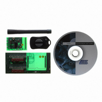
... RF Transmitter Application Board – Tiny13 + T5750 (868/915 MHz) CD containing sample software One CR2032 battery External whip antenna (RX only, TX antenna is PCB trace) Optional items not included in the kit: Atmel AVR STK500 Starter Kit and Development System 1-2 4842B–AVR–10/09 STK511 User Guide ...
Page 6
... Configuring the Receiver Atmel RF Receivers designated ATA5743, ATA5760 and ATA5761 contain two configuration registers (Atmel RF receiver designated ATA5744 does not). These registers control the digital processing of the incoming RF signal, as well as define the receivers’ polling interval. The register values are stored in vol- atile memory and are lost when power is removed ...
Page 7
Getting Started 1. Once the hardware is setup, verify that the DATA selector switch is in the STK511 position. 2. Apply power, locate the DIP switch corresponding to the OPMODE register, and set the 5th DIP switch to the ON ...
Page 8
STK511 Receiver Interface Board Configuration 1. Verify that the Receiver Application Board has been inserted into the appropriate sockets on the STK511 Receiver Interface Board. 2. Connect the STK511 Receiver Interface Board to the STK500 by aligning EXPAND0 and ...
Page 9
... Mode Selection Unique to the Atmel ATA5743 only is the MODE input. This input changes the IC's internal basic clock cycle and can affect the polling duty cycle and Bit Check timing limits. If the receiver board was built for 315 MHz operation, the MODE input was connected to ground. If the board was built for 434 MHz, oper- ation, the MODE input was connected to + supply ...
Page 10
STK511 Receiver Board 3.1.5 XTAL Oscillator The internal local oscillator (LO) for the receiver is determined by a scaled representation of the crystal frequency. The scale factor is different for each receiver. The ATA5743 receiver uses the crystal fre- quency ...
Page 11
... PortB. Also the D_CLK (Data Clock) line, provided by the RF receiver, is routed to bit 2 of PortB. For this demo, the RF signal is in Manchester format possible to decode the data by measuring edge-to-edge timing of this line, but many Atmel receivers simplify this task by recovering the clock from the DATA signal. This clock can be found on the D_CLK line and will only appear when a predefined number of logic 1s (set in the OPMODE register under Bit Check) are followed by a logic 0 ...
Page 12
STK511 Receiver Board timeOut = 0; // Look for D_CLK to end pulse. if(flag1) { while(!flag2 && timeOut < timeOutVal Check D_CLK. Exit when high if(PINB.2 == 1){flag2 = 1;} // Increment timeout else if(PINB.2 == 0){timeOut++;} } ...
Page 13
Check for two of the three bytes received to match before displaying if(ReceiveData[0] == ReceiveData[1] || ReceiveData[0] == ReceiveData[2]) { DisplayData = ReceiveData[0];// Load data to be displayed delay_ms(40); DisplayLED(); } // Check for two of the ...
Page 14
STK511 Receiver Board DisplayData = ReceiveData[1]; delay_ms(40); DisplayLED(); } delay_ms(40);// Wait ResetRX(); } } 3-6 4842B–AVR–10/09 // Load data to be displayed // Wait // Write to LEDs // Set the Receiver back to polling STK511 User Guide ...
Page 15
Hardware Description Figure 4-1. STK511 Configuration Options STK511 Receiver Interface Board ( Stand-alone configuration Figure 4-4 on page 4-2 ( Figure 4-2. STK511 Receiver Interface Board Figure 4-3. Receiver Application Board STK511 User Guide STK511 Receiver Interface Board Figure ...
Page 16
... Standalone Configuration The STK511 Receiver Interface Board can be used in a standalone configuration along with one of Atmel’s Receiver Application Boards (see bined with the Receiver Interface Board and connected to an external 5 volt power supply, it’s configuration registers can be programmed and the resulting demodulation performance can be evalu- ated ...
Page 17
... Receiver Connectors As stated previously, the STK511 Receiver Interface Board was designed to interface with Atmel’s RF Receiver Application Boards. There are two rows of connectors (labeled U2) on the STK511 Receiver Interface Board that accept the Receiver Application Boards. These twelve pin connectors allow the receiver board to communicate with the STK511 Receiver Interface Board firmware, as well as route sig- nals to the sockets provided on the STK500 AVR Development board ...
Page 18
STK511 Receiver Interface Board The following table shows how the signals from the receiver connectors (U2) are routed to the microcon- troller I/O ports. As shipped, the STK511 Receiver Interface Board routes the Receiver Application Board signals, necessary for stand-alone ...
Page 19
... The DATA selector switch controls the routing of the bi-directional DATA line coming from the Receiver Application Board. The switch either routes the DATA line to the STK511 Receiver Interface Board's on- board microcontroller or to the Atmel AVR microcontroller on the STK500 board. The silkscreen legend designates the selected mode based on switch position. To enable the Receiver Application Board, a low pulse must be applied to the DATA line whenever power is applied (see receiver datasheet “ ...
Page 20
... Programs the OPMODE and LIMIT registers via the bi-directional DATA line Holds the receiver in a polling mode via the POL/ON line Many Atmel receivers generate a Reset Marker signal, consisting of a 128 kHz square wave, upon power up. This must be cleared before normal operation can occur. Applying low pulse to the DATA line clears the Reset Marker ...
Page 21
... When the Configure button is pressed, several things occur. First, the actual settings of the DIP Switches are checked by reading ports A, C, and D. The settings are then programmed into the receiver according to the Atmel bi-directional, one-wire interface protocol. The serial programming sequence is repeated twice for each of the registers. Verification of the programmed data is accomplished by checking for the presence of an acknowledge pulse ...
Page 22
STK511 Receiver Interface Board cTempByte = *e_eeprom_ptr++;// Load LSB of LIMIT reg and decrement for(cBitPos = 8; cBitPos > 0; cBitPos--) { //-- Sync: while(TestBit(PINB,RX_DATA// Wait to Synchronization pulse begin { } delay_us(50); while(!(TestBit(PINB,RX_DATA)// Wait to Synchronization pulse end { ...
Page 23
Sync: while(TestBit(PINB,RX_DATA)) // Wait to Synchronization pulse { } delay_us(50); while(!(TestBit(PINB,RX_DATA))) // Wait to Synchronization pulse end { } delay_us(50); //-- Program: if(!(TestBit(cTempByte,cBitPos-1// If the current bit is low delay_us(50); // Short Delay } } delay_us(2000); ...
Page 24
... Overview Supplied with this kit is a single-frequency UHF RF transmitter, operating on 315, 433.92, 868.3, or 915 MHz. It employs the Atmel T575x series of UHF transmitter ICs and the Atmel AVR microcontroller IC. The transmitter is housed in a 2-button key fob with openings in the fob that expose two LED activity- indicators, a CdS photocell, and a 6-pin header for microcontroller programming (see Figure 5-1 ...
Page 25
... ISP Header Pinout (Viewed from the Top of the Fob) Figure 5-3. Transmitter Programming Assembly Using Atmel’s AVR Studio on the accompanying CD can be easily loaded. The assembly-language code is well commented and should enable the user to modify such things as the Manchester-encoded transmission data rate and duty cycle, or the update interval for light-sensor ...
Page 26
... Internal RC Oscillator: The ATtiny13 contains a fuse-selectable, calibrated internal RC oscillator, which provides a 4.8 MHz or 9.6 MHz clock. No external components are required. The accuracy of the oscilla- tor is ±10% of the nominal frequency. Atmel Application Note AVR053 outlines a method to re-calibrate the oscillator to an accuracy approaching ±1%. ...
Page 27
STK511 Transmitter Board Keying Circuit: RF transmission from the T575x is controlled by signals on its two ports ENABLE and PA_ENABLE. These signals originate from the ATtiny13's ports PB4 and PB1, respectively. With this straightforward, two-line control, ASK modulation (or ...
Page 28
Software Description 5.2.1 Overview There are two sample programs included on the accompanying CD that demonstrate the transmitter's functional capabilities. One called STK511 TX UpDown, increments and decrements a counter and transmits the count value. The other, called STK511 ...
Page 29
STK511 Transmitter Board KeepAlive: RJMP ; - - - - - - - - - - - - - - - - - - - - - - - - - - - - - - - - - - ...
Page 30
LDI RJMP ISRPinS1: LDI OUT LDI OUT LDI RJMP ISRPinS2: LDI OUT LDI OUT LDI RJMP ISRPinLoop: WDR IN ANDI BRNE RCALL ISRPinChgEnd: LDI OUT SEI OUT POP RETI STK511 User Guide mode,ASK ; TP - Set mode to ASk ...
Page 31
STK511 Transmitter Board ; - - - - - - - - - - - - - - - - - - - - - - - - - - - - - - - - - - - - ...
Page 32
... General This kit is intended to showcase the broad flexibility of Atmel's RF radio chip-set by offering multiple transmission modes that span frequencies across the RF spectrum from 315 MHz to 915 MHz. Conse- quently, local regulatory limitations will apply that restrict certain combinations of transmission modes and RF spectrum. These regulations generally place restrictions on carrier frequency, transmission duty cycle, harmonic content, and method of measurement ...
Page 33
Regulatory Requirements 6.3 Operating Frequency The Federal Communications Committee (FCC) governs the use of RF spectrum in the United States. The European Telecommunications Standards Institute (ETSI) covers this in Europe. The FCC allows the type of RF transmissions generated by ...
Page 34
Table 7-1. Troubleshooting Solutions Problem LED on Receiver Application Board not active LED(s) on Receiver Interface Board not active STK511 User Guide Troubleshooting Guide Reason Power is not applied or is less than 5V DATA Selector switch was not set ...
Page 35
Troubleshooting Guide Table 7-1. Troubleshooting Solutions (Continued) Problem Registers in the receiver do not appear to be programming Unable to load Receiver Interface Board firmware Transmitter not responding to button press No activity on Transmitter Application Board LED(s) 7-2 4842B–AVR–10/09 ...
Page 36
Table 7-1. Troubleshooting Solutions (Continued) Problem Transmitter Application Board LED(s) constantly lit Unable to program Transmitter Application board through ISP header Demo not working (STK500 LED(s) not responding to transmitted signal) STK511 User Guide Reason Demo Software corrupted Incorrect orientation ...
Page 37
... Disclaimer: The information in this document is provided in connection with Atmel products. No license, express or implied, by estoppel or otherwise, to any intellectual property right is granted by this document or in connection with the sale of Atmel products. EXCEPT AS SET FORTH IN ATMEL’S TERMS AND CONDI- TIONS OF SALE LOCATED ON ATMEL’S WEB SITE, ATMEL ASSUMES NO LIABILITY WHATSOEVER AND DISCLAIMS ANY EXPRESS, IMPLIED OR STATUTORY WARRANTY RELATING TO ITS PRODUCTS INCLUDING, BUT NOT LIMITED TO, THE IMPLIED WARRANTY OF MERCHANTABILITY, FITNESS FOR A PARTICULAR PURPOSE, OR NON-INFRINGEMENT ...