ATAKSTK511-3 Atmel, ATAKSTK511-3 Datasheet - Page 18
ATAKSTK511-3
Manufacturer Part Number
ATAKSTK511-3
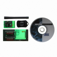
Description
KIT RF MODULE 315MHZ FOR STK500
Manufacturer
Atmel
Series
SmartRF®r
Type
Transmitter, Receiver, ASK, FSKr
Specifications of ATAKSTK511-3
Frequency
433MHz
Wireless Frequency
315 MHz
For Use With/related Products
ATSTK500
Lead Free Status / RoHS Status
Contains lead / RoHS non-compliant
Other names
Q2262874


4842B–AVR–10/09
STK511 Receiver Interface Board
4.2.2
4-4
Configuration Register DIP Switches
The following table shows how the signals from the receiver connectors (U2) are routed to the microcon-
troller I/O ports. As shipped, the STK511 Receiver Interface Board routes the Receiver Application
Board signals, necessary for stand-alone operation, to the on-board microcontroller. The remaining sig-
nals are routed to the STK500 through the expansion connectors. See section
on page 4-6
Upon receiving power, the receiver’s OPMODE and LIMIT registers contain default settings. Any values
other than the default require programming. The OPMODE register controls Baud Rate range, Bit Check
quantity, Modulation type, Sleep polling time, and Noise Suppression. The LIMIT register controls the
maximum and minimum valid time between edges. See the receiver datasheet for more information on
the registers.
The DIP switches on the STK511 Receiver Interface Board allow individual bits in these registers to be
modified. As an added convenience, the STK511 Receiver Interface Board contains a silkscreen legend
that specifies each bit function for both registers as well as their corresponding default value.
The configuration register DIP switches connect to the following I/O ports of the ATmega8515 AVR
microcontroller which is integral to the STK511 Receiver Interface Board. The bits not listed in the table
below are set to constants in the firmware.
Table 4-1. DIP Switch to I/O Port Mapping
Bit1
Bit1
---
---
U2 Connector
Bit2
Bit2
Pin #
---
---
12
11
10
9
8
7
6
5
4
3
2
1
for additional information.
PD0
Bit3
Bit3
PA0
Receiver Signal to I/O Port Mapping
PD1
Bit4
Bit4
PA1
IC_Active
ATA5743
POL/ON
PD2
Bit5
Bit5
PA2
D_CLK
MODE
SENS
DATA
GND
VCC
---
---
---
---
PD3
Bit6
Bit6
PA3
Receiver Application Board
PD4
PA4
Bit7
Bit7
OPMODE Register
LIMIT Register
IC_ACTIVE
ATA5760/1
PD5
POL/ON
PA5
Bit8
Bit8
D_CLK
SENS
V DIV
DATA
GND
VCC
---
---
---
---
PD6
PA6
Bit9
Bit9
Bit10
Bit10
PD7
PA7
ATA5744
ENABLE
Bit11
Bit11
PC0
PC4
DATA
RSSI
VCC
GND
BR0
BR1
---
---
---
---
---
Bit12
Bit12
PC1
PC5
“Receive Signal Routing”
Bit13
Bit13
PC2
PC6
Microcontroller I/O
STK511 User Guide
Bit14
Bit14
PC3
PC7
Port
PB4
PB1
PB3
PB2
PB1
PB0
---
---
---
---
---
---
Bit15
Bit15
---
---
Related parts for ATAKSTK511-3
Image
Part Number
Description
Manufacturer
Datasheet
Request
R

Part Number:
Description:
DEV KIT FOR AVR/AVR32
Manufacturer:
Atmel
Datasheet:

Part Number:
Description:
INTERVAL AND WIPE/WASH WIPER CONTROL IC WITH DELAY
Manufacturer:
ATMEL Corporation
Datasheet:
Part Number:
Description:
Low-Voltage Voice-Switched IC for Hands-Free Operation
Manufacturer:
ATMEL Corporation
Datasheet:
Part Number:
Description:
MONOLITHIC INTEGRATED FEATUREPHONE CIRCUIT
Manufacturer:
ATMEL Corporation
Datasheet:
Part Number:
Description:
AM-FM Receiver IC U4255BM-M
Manufacturer:
ATMEL Corporation
Datasheet:
Part Number:
Description:
Monolithic Integrated Feature Phone Circuit
Manufacturer:
ATMEL Corporation
Datasheet:
Part Number:
Description:
Multistandard Video-IF and Quasi Parallel Sound Processing
Manufacturer:
ATMEL Corporation
Datasheet:
Part Number:
Description:
High-performance EE PLD
Manufacturer:
ATMEL Corporation
Datasheet:
Part Number:
Description:
8-bit Flash Microcontroller
Manufacturer:
ATMEL Corporation
Datasheet:
Part Number:
Description:
2-Wire Serial EEPROM
Manufacturer:
ATMEL Corporation
Datasheet: