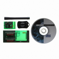
ATAKSTK511-3 Atmel, ATAKSTK511-3 Datasheet - Page 9

ATAKSTK511-3
Manufacturer Part Number
ATAKSTK511-3
Description
KIT RF MODULE 315MHZ FOR STK500
Manufacturer
Atmel
Series
SmartRF®r
Type
Transmitter, Receiver, ASK, FSKr
Specifications of ATAKSTK511-3
Frequency
433MHz
Wireless Frequency
315 MHz
For Use With/related Products
ATSTK500
Lead Free Status / RoHS Status
Contains lead / RoHS non-compliant
Other names
Q2262874
3.1
3.1.1
3.1.2
3.1.3
3.1.4
STK511 User Guide
Hardware Description
Overview
IC_Active LED
CDEM Capacitor
Mode Selection
The Atmel UHF receivers ATA5743, ATA5760, and ATA5761 are considered intelligent receivers. They
demodulate and process the incoming ASK or FSK RF signal before providing a digital output to the
user. These receivers are well suited for low cost, low data rate transmissions. For more detail about the
receiver IC, refer to its respective datasheet. This section will focus on the design and features of the
Receiver Application Board.
The IC_Active signal on the Receiver Application Board provides status of receiver IC activity. If it is low,
then the receiver is in sleep mode. When the receiver is in the active mode, the IC_Active line is driven
high. The LED on the Receiver Application Board gives a visual indication of the value of this signal by
turning on when IC_Active is high. When selected, polling will cause the IC_Active signal to pulse. This
may cause the LED to illuminate less brightly. This is normal and provides the user with an intuitive indi-
cation of how often the receiver IC is in the active mode.
The CDEM capacitor, on the Receiver Application Board, works in conjunction with the Baud Range to
set the data bandpass filter corner frequencies. The Baud Range is set in the receiver configuration reg-
isters and establishes the upper corner frequency, while the CDEM capacitor establishes the lower
corner frequency of the data bandpass filter. A sufficiently large capacitor value must be used to allow
the lowest frequency of the data to pass through. However, too large a capacitance results in poor set-
tling times and can skew or truncate incoming RF data. For suggested capacitance values for different
Baud Rates, refer to the individual receiver datasheets.
Unique to the Atmel ATA5743 only is the MODE input. This input changes the IC's internal basic clock
cycle and can affect the polling duty cycle and Bit Check timing limits. If the receiver board was built for
315 MHz operation, the MODE input was connected to ground. If the board was built for 434 MHz, oper-
ation, the MODE input was connected to + supply. The proper connection of the MODE input is achieved
using resistor network R5/R6. 315 MHz operation corresponds to R5 unpopulated and R6 a 0
434 MHz operation corresponds to R5 populated with a 0 resistor and R6 left unpopulated.
Note:
Changes to the MODE input also requires changes to the crystal oscillator, loop filter, LNA, and antenna
matching components. It is strongly recommended that the datasheet be referenced before attempting to
make changes to the operating frequency.
STK511 Receiver Board
Section 3
4842B–AVR–10/09
resistor.
3-1


